Sign In
Upload
Manuals
Brands
Vaisala Manuals
Transmitter
DRYCAP DMT348
Vaisala DRYCAP DMT348 Manuals
Manuals and User Guides for Vaisala DRYCAP DMT348. We have
2
Vaisala DRYCAP DMT348 manuals available for free PDF download: User Manual
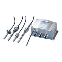
Vaisala DRYCAP DMT348 User Manual (196 pages)
Dewpoint and Temperature Transmitter
Brand:
Vaisala
| Category:
Transmitter
| Size: 2.49 MB
Table of Contents
Table of Contents
3
Vaisala
3
Vaisala
5
Chapter 1 General Information
13
About this Manual
13
Contents of this Manual
13
Chapter 2
13
Version Information
14
Documentation Conventions
14
Table 1 Manual Revisions
14
Recycling
15
Safety
15
ESD Protection
15
Regulatory Compliances
16
EU Declaration of Conformity
16
Transmitters with LAN or WLAN Interface
16
Transmitters with WLAN Interface
17
License Agreement
17
Patent Notice
17
Trademarks
17
Warranty
18
Chapter 2 Product Overview
19
Introduction to DMT340
19
Table 2 Quantities and Their Abbreviations
19
Basic Features and Options
20
Table 3 Optional Quantities and Their Abbreviations
20
Figure 1 Transmitter Body
21
Structure of the Transmitter
21
Figure 2 Inside the Transmitter
22
Figure 3 Probe Options
23
Probe Options
23
Chapter 3 Installation
25
Mounting the Housing
25
Standard Mounting Without Mounting Plate
25
Figure 4 Standard Mounting
25
Wall Mounting with Wall Mounting Kit
26
Figure 5 Mounting with Wall Mounting Kit
26
Figure 6 Dimensions of the Plastic Mounting Plate (MM/Inch)
26
Figure 7 Mounting with Metal Wall Mounting Plate
27
Figure 8 Dimensions of Metal Mounting Plate (MM/Inch)
27
Mounting with DIN Rail Installation Kit
28
Figure 9 Mounting with DIN Rail Installation Kit
28
Pole Installation with Installation Kit for Pole or Pipeline
29
Figure 10 Vertical Pole
29
Figure 11 Horizontal Pole
29
Mounting the Rain Shield with Installation Kit
30
Panel Mounting Frame
30
Figure 12 Mounting the Rain Shield with Installation Kit
30
Figure 13 Panel Mounting Frame
31
Figure 14 Panel Mounting Dimensions (MM/Inch)
31
Wiring
32
Cable Bushings
32
Figure 15 Cable Bushings
32
Figure 16 Grounding the Screen of Electrical Cable
33
Grounding the Cables
33
Figure 17 Screw Terminal Block on the Motherboard
34
Signal and Power Supply Wiring
34
Transmitter Housing Grounding
34
Connections to a 24 VAC Power Supply
36
Figure 18 Connections to 24 VAC Power Supply
36
Probe Mounting
37
DMT342 Small-Size Flanged Probe for Use with Sampling Cell
37
Figure 19 DMT342 Installation (Without the Sampling Cell)
37
Figure 20 HMP302SC Optional Sampling Cell
38
DMT344 for High-Pressure Applications
39
Figure 21 DMT344 Probe
39
Figure 22 Tightening the Nut
40
Figure 23 Cleaning of the Tightening Cone
40
DMT347 Small Pressure-Tight Probe
41
Pressure-Tight Swagelok Installation Kits for DMT347
41
Figure 24 DMT347 Probe with Swagelok Installation Kit
41
Figure 25 DMT347 Probe Installation to Pipeline with Swagelok Installation Kit
42
DMT348 for Pressurized Pipelines
43
Figure 26 DMT348 Probe
43
Figure 27 Leak Screw in the DMT348 Probe
44
Figure 28 Sealing of Fitting Body into Process
44
Table 4 DMT348 Probe Dimensions
44
Tightening the Clasp Nut
45
Figure 29 Tightening the Clasp Nut
45
Ball Valve Installation Kit for DMT348
47
Figure 30 Installing the DMT348 Probe through a Ball Valve Assembly
47
Leak Screw Installation
49
Figure 31 Probe in Leak Screw Installation
49
Mounting the Probe Directly to the Process
50
Figure 32 DM240FA with Probe
50
Figure 33 Example of Installing the Probe Directly on the Process Pipe
51
Sampling Cell for DMT348
52
Figure 34 Sampling Cells DMT242SC2 and DMT242SC
52
Figure 35 Installing the Probe in High Temperatures
53
Optional Modules
54
Power Supply Module
54
Figure 36 Power Supply Module
54
Installation
55
Warnings
56
Galvanic Isolation for Output
59
Installation
59
Third Analog Output
59
Figure 37 Galvanic Output Isolation Module
59
Figure 38 Third Analog Output
59
Figure 39 Third Analog Output Selection
60
Installation and Wiring
60
Alarm Relays
61
Installation and Wiring
61
Selecting the Activation State of the Relay
61
Figure 40 Relay Module
62
RS-422/485 Interface
63
Figure 41 RS-422/485 Module
63
Installation and Wiring
64
Table 5 Connecting the Twisted Pair Wires to the Screw Terminals
64
Figure 42 4-Wire RS-485 Bus
65
Table 6 4-Wire (Switch 3: On)
65
Figure 43 2-Wire RS-485 Bus
66
Table 7 2-Wire (Switch 3: Off)
66
LAN Interface
67
WLAN Interface
68
Figure 44 LAN Interface Module
68
Attaching the WLAN Antenna
69
Figure 45 WLAN Interface Module
69
Data Logger Module
70
Table 8 Observation Periods and Resolution
70
Figure 46 Data Logger Module
71
8-Pin Connector
72
Figure 47 Pinout of the Optional 8-Pin Connector
72
Table 9 Wiring of the Optional 8-Pin Connector
72
Chapter 4 Operation
73
Getting Started
73
Display/Keypad
74
Basic Display
74
Figure 48 Basic Display
74
Graphic History
75
Figure 49 Graphical Display
75
Table 10 Periods for Trend and Max/Min Calculations
75
Figure 50 Graphical Display with Data Logger
76
Table 11 Graph Information Messages
76
Menus and Navigation
77
Figure 51 Main Views
77
Changing the Language
78
Display Backlight Setting
78
Rounding Setting
78
Display Contrast Setting
79
Keypad Lock (Keyguard)
79
Menu PIN Lock
79
Factory Settings
80
Display Alarms
80
Configuring a Display Alarm
81
Figure 52 Alarm Limits Shown on Graph Screen
81
Figure 53 Display Alarm Active
81
Figure 54 Display Alarms
82
Figure 55 Modifying an Alarm Limit
82
MI70 Link Program for Data Handling
83
Serial Line Communication
84
Figure 56 Service Port Connector and User Port Terminal on the Motherboard
84
User Port Connection
85
Figure 57 Connection Example between PC Serial Port and User Port
85
Table 12 Default Serial Communication Settings for the User Port
85
User Port Operating Modes
85
Service Port Connection
86
Connection Cables
86
Installing the Driver for the USB Cable
86
Using the Service Port
87
LAN Communication
87
Table 13 Communication Settings for the Service Port
87
IP Configuration
88
Table 14 IP Settings for the LAN and WLAN Interfaces
88
Using Display/Keypad
88
Figure 58 Network Interface Menu
89
Figure 59 IP Configuration Menu
89
Using Serial Line
90
Wireless LAN Configuration
91
Table 15 Wireless LAN Settings
91
Figure 60 Wireless LAN Settings
92
Figure 61 Entering Network SSID
92
Figure 62 Selecting the Wireless Network Type
92
Using Display/Keypad
92
Using Serial Line
93
Communication Protocol
94
Web Configuration for LAN and WLAN
94
Figure 63 Web Configuration Interface for WLAN
95
Terminal Program Settings
95
Figure 64 Opening a Serial Connection
96
Opening a Serial/Usb Connection
96
Figure 65 Opening a Telnet Connection
97
Opening a Telnet Session (LAN/WLAN)
97
List of Serial Commands
98
Table 16 Measurement Commands
98
Table 17 Formatting Commands
98
Table 18 Data Recording Commands
99
Table 19 Purge Commands
99
Table 20 Autocalibration Commands
99
Table 21 Calibration and Adjustment Commands
99
Table 22 Setting and Testing the Analog Outputs
99
Table 23 Setting and Testing the Relays
99
Table 24 Other Commands
100
Getting the Measurement Message from Serial Line
101
Outputting Reading Once
101
Starting Continuous Outputting
101
Stopping Continuous Outputting
101
Assign an Alias for the SEND Command
102
Communicating with a Transmitter in POLL Mode
102
Close
102
Open
102
Formatting Serial Line Message
103
FTIME and FDATE
103
Fst
104
General Settings
105
Changing the Quantities and Units
105
Using Display/Keypad
105
Form
106
Table 25 FORM Command Modifiers
106
Using Serial Line
106
Unit
107
Pressure Compensation Setting
108
Using Display/Keypad
108
Figure 66 Pressure Set Buttons on the Motherboard
109
Using Buttons on the Motherboard
109
Using Serial Line
109
XPRES and PRES
109
Date and Time
110
Table 26 Conversion Factors for Pressure Units
110
Using Display/Keypad
110
Data Filtering
111
Table 27 Filtering Levels
111
Using Serial Line
111
Device Information
112
Figure 67 Device Information on Display
112
Filt
112
Help
114
Light
114
Errs
115
Reset
115
Resetting the Transmitter Using Serial Line
115
Vers
115
Lock
116
Locking Menu/Keypad Using Serial Line
116
Serial Output Settings
117
Using Display/Keypad
117
Seri
118
Using Serial Line
118
Addr
119
Smode
119
Table 28 Selection of Output Modes
119
Intv
120
Sdelay
120
Echo
121
Data Recording
122
Dsel
122
Selecting the Data Recording Quantities
122
Dir
123
View Recorded Data
123
Play
124
Analog Output Settings
125
Changing the Output Mode and Range
125
Deleting the Recorded Files
125
Undelete
125
Figure 68 Current/Voltage Switches of Output Modules
126
Analog Output Quantities
127
Amode/Asel
128
Analog Output Tests
129
Itest
129
Aerr
130
Analog Output Fault Indication Setting
130
Measurement-Based Relay Output Modes
131
Operation of Relays
131
Quantity for Relay Output
131
Relay Setpoints
131
Figure 69 Measurement-Based Relay Output Modes
132
Hysteresis
133
Relay Indicating Transmitter Error Status
133
Figure 70 FAULT/ONLINE STATUS Relay Output Modes
134
Enabling/Disabling the Relays
135
Table 29 Relay State Examples
135
Figure 71 Relay Availability
136
Operation of the Indication Leds
136
Setting the Relay Outputs
136
Rsel
137
Rtest
139
Testing the Operation of Relays
139
Autocal
140
Automatic Autocal
140
Sensor Functions
140
Figure 72 Following Autocal on the Display
141
Manual Autocal
141
Sensor Purge
141
Figure 73 Sensor Purge Settings
142
Figure 74 Performing Sensor Purge
142
Starting and Configuring Sensor Purge
142
Using Display/Keypad (Optional)
142
Pur
143
Purge
143
Using Serial Line
143
Sensor Warming
144
Chapter 5 Modbus
145
Overview of MODBUS Protocol Support
145
Table 30 Supported MODBUS Variants
145
Taking MODBUS into Use
146
Enabling Serial MODBUS
147
Figure 75 Serial Interface Settings
147
Using Display/Keypad (Optional)
147
Using Serial Line
147
Enabling Ethernet MODBUS
149
Figure 76 IP Configuration
149
Figure 77 Wireless LAN Settings
149
Using Display/Keypad (Optional)
149
Figure 78 Communication Protocol
150
Using Serial Line
150
Diagnostic MODBUS Counters
152
Figure 79 MODBUS Counters
152
Viewing Counters Using Display/Keypad
152
Viewing Counters Using Service Port
152
Disabling MODBUS
153
Chapter 6 Maintenance
155
Periodic Maintenance
155
Cleaning
155
Changing the Probe Filter
155
Calibration and Adjustment
155
Error States
156
Figure 80 Error Indicator and Error Message
156
Table 31 Error Messages
157
Technical Support
158
Product Returns
158
Chapter 7 Calibration and Adjustment
159
Calibration
159
User Calibration and Adjustment
159
Opening and Closing the Adjustment Mode
160
Table 32 Indicator Led Functions
160
Adjustment Information
161
CTEXT and CDATE
161
Adjusting Dewpoint Two-Point
162
Figure 81 Starting the Adjustment
162
Figure 82 Performing Purge
162
Two-Point Relative Humidity Adjustment Using Display/Keypad
162
Figure 83 Following the RH Trend on Graphical Display
163
Figure 84 Ending Adjustment of Point 1
163
Figure 85 Proceeding to Adjustment of Point 2
163
Figure 86 Completing Adjustment of Point 2
163
One-Point Dewpoint Adjustment Using Display/Keypad
164
Two-Point Relative Humidity Adjustment Using Serial Line
164
Figure 87 Following Stabilization
165
Figure 88 Proceeding with T
165
Figure 89 Completing T
165
One-Point Dewpoint Adjustment Using Serial Line
166
Adjusting Temperature
167
Adjusting Temperature Using Display/Keypad
167
Adjusting Temperature Using Serial Line
168
Adjusting Analog Outputs
169
Adjusting Analog Outputs Using Display/Keypad
169
Acal
170
Adjusting Analog Outputs Using Serial Line
170
Chapter 8 Technical Data
171
Specifications
171
Performance
171
Figure 90 Dewpoint Accuracy Graph
171
Operating Environment
172
Inputs and Outputs
172
Mechanics
173
Probe Specifications
173
Technical Specifications of Optional Modules
174
Analog Output Module
174
Power Supply Module
174
Relay Module
174
Data Logger Module
175
LAN Interface Module
175
RS-485 Module
175
WLAN Interface Module
175
Options and Accessories
176
Table 33 Options and Accessories
176
Dimensions (MM/Inch)
178
Figure 91 DMT340 Transmitter Body Dimensions
178
Figure 92 WLAN Antenna Dimensions
179
Figure 93 Sampling Cell Dimensions
179
Figure 94 DMT342 Probe Dimensions
180
Figure 95 DMT344 Probe Dimensions
180
Figure 96 DMT347 Probe Dimensions
181
Figure 97 DMT348 Standard Probe Dimensions
181
Figure 98 NPT 1/2" Nut Dimensions
182
Figure 99 DMT348 Optional 400Mm Probe Dimensions
182
Appendix Acalculation Formulas
183
Appendix B Modbus Reference
187
Function Codes
187
Table 34 Supported Function Codes
187
Register Map
188
Data Encoding
188
32-Bit Floating Point Format
188
Table 35 DMT340 MODBUS Register Blocks
188
16-Bit Integer Format
189
Measurement Data (Read-Only)
190
Table 36 Measurement Data Registers
190
Status Registers (Read-Only)
191
Configuration Registers
191
Table 37 Status Registers
191
Table 38 Configuration Parameter Registers
191
Exception Status Outputs
192
Table 39 Configuration Flag Registers
192
Table 40 DMT340 Exception Status Outputs
192
Diagnostic Sub-Functions
193
Table 41 DMT340 MODBUS Diagnostics
193
Device Identification Objects
194
Exception Responses
194
Table 42 DMT340 MODBUS Device Identification
194
Table 43 DMT340 MODBUS Exception Responses
194
Advertisement
Vaisala DRYCAP DMT348 User Manual (169 pages)
Dewpoint and Temperature Transmitter
Brand:
Vaisala
| Category:
Transmitter
| Size: 2.62 MB
Table of Contents
Table of Contents
3
Vaisala
3
Vaisala
5
Chapter 1 General Information
13
About this Manual
13
Contents of this Manual
13
Chapter 2
13
Version Information
14
General Safety Considerations
14
Feedback
14
Product Related Safety Precautions
15
ESD Protection
15
Recycling
15
Regulatory Compliances
16
DNV Type Approval
16
Transmitters with LAN or WLAN Interface
16
Transmitters with WLAN Interface
17
Patent Notice
17
Trademarks
17
License Agreement
18
Warranty
18
Chapter 2 Product Overview
19
Introduction to DMT340
19
Basic Features and Options
20
Structure of the Transmitter
21
Figure 1 Transmitter Body
21
Figure 2 Inside the Transmitter
22
Probe Options
23
Figure 3 Probe Options
23
Chapter 3 Installation
25
Mounting the Housing
25
Standard Mounting Without Mounting Plate
25
Figure 4 Standard Mounting
25
Wall Mounting with Wall Mounting Kit
26
Figure 5 Mounting with Wall Mounting Kit
26
Figure 6 Dimensions of the Plastic Mounting Plate (MM/Inch)
26
Figure 7 Mounting with Metal Wall Mounting Plate
27
Figure 8 Dimensions of Metal Mounting Plate (MM/Inch)
27
Mounting with DIN Rail Installation Kit
28
Figure 9 Mounting with DIN Rail Installation Kit
28
Pole Installation with Installation Kit for Pole or Pipeline
29
Figure 10 Vertical Pole
29
Figure 11 Horizontal Pole
29
Mounting the Rain Shield with Installation Kit
30
Panel Mounting Frame
30
Figure 12 Mounting the Rain Shield with Installation Kit
30
Figure 13 Panel Mounting Frame
31
Figure 14 Panel Mounting Dimensions (MM/Inch)
31
Wiring
32
Cable Bushings
32
Figure 15 Cable Bushings
32
Grounding the Cables
33
Figure 16 Grounding the Screen of Electrical Cable
33
Transmitter Housing Grounding
34
Signal and Power Supply Wiring
34
Figure 17 Screw Terminal Block on the Motherboard
34
Connections to a 24 VAC Power Supply
35
Probe Mounting
36
Figure 18 Connections to 24 VAC Power Supply
36
DMT342 Small-Size Flanged Probe for Use with Sampling Cell
37
Figure 19 DMT342 Installation (Without the Sampling Cell)
37
Figure 20 HMP302SC Optional Sampling Cell
38
DMT344 for High-Pressure Applications
39
Figure 21 DMT344 Probe
39
Figure 22 Tightening the Nut
40
Figure 23 Cleaning of the Tightening Cone
40
DMT347 Small Pressure-Tight Probe
41
Pressure-Tight Swagelok Installation Kits for DMT347
41
Figure 24 DMT347 Probe with Swagelok Installation Kit
41
Figure 25 DMT347 Probe Installation to Pipeline with Swagelok Installation Kit
42
DMT348 for Pressurized Pipelines
43
Figure 26 DMT348 Probe
43
Figure 27 Leak Screw in the DMT348 Probe
44
Figure 28 Sealing of Fitting Body into Process
44
Tightening the Clasp Nut
45
Figure 29 Tightening the Clasp Nut
45
Ball Valve Installation Kit for DMT348
46
Figure 30 Installing the DMT348 Probe through a Ball Valve Assembly
47
Leak Screw Installation
49
Figure 31 Probe in Leak Screw Installation
49
Mounting the Probe Directly to the Process
50
Figure 32 DM240FA with Probe
50
Figure 33 Example of Installing the Probe Directly on the Process Pipe
51
Sampling Cell for DMT348
52
Figure 34 Sampling Cells DMT242SC2 and DMT242SC
52
Figure 35 Installing the Probe in High Temperatures
53
Optional Modules
54
Power Supply Module
54
Figure 36 Power Supply Module
54
Installation
55
Warnings
55
Galvanic Isolation for Output
58
Installation
58
Figure 37 Galvanic Output Isolation Module
58
Third Analog Output
59
Installation and Wiring
59
Figure 38 Third Analog Output
59
Alarm Relays
60
Installation and Wiring
60
Figure 39 Third Analog Output Selection
60
Selecting the Activation State of the Relay
61
Figure 40 Relay Module
61
RS-422/485 Interface
62
Installation and Wiring
62
Figure 41 RS-485-Module
62
Figure 42 4-Wire RS-485 Bus
63
LAN Interface
64
WLAN Interface
65
Figure 43 LAN Interface Module
65
Attaching the WLAN Antenna
66
Data Logger Module
66
Figure 44 WLAN Interface Module
66
Figure 45 Data Logger Module
68
8-Pin Connector
69
Figure 46 Wiring of the Optional 8-Pin Connector
69
Chapter 4 Operation
71
Getting Started
71
Display/Keypad
71
Basic Display
71
Graphic History
72
Figure 47 Basic Display
72
Figure 48 Graphical Display
72
Figure 49 Graphical Display with Data Logger
73
Menus and Navigation
74
Changing the Language
75
Figure 50 Main Views
75
Rounding Setting
76
Display Backlight Setting
76
Display Contrast Setting
76
Keypad Lock (Keyguard)
76
Menu PIN Lock
77
Factory Settings
77
Display Alarms
78
Configuring a Display Alarm
78
Figure 51 Display Alarm Active
78
Figure 52 Display Alarms
79
Figure 53 Modifying an Alarm Limit
79
MI70 Link Program for Data Handling
80
Serial Line Communication
80
User Port Connection
81
Figure 54 Service Port Connector and User Port Terminal on the Mother Board
81
Service Port Connection
82
Connection Cables
82
Installing the Driver for the USB Cable
82
Figure 55 Connection Example between PC Serial Port and User Port
82
Using the Service Port
83
LAN Communication
84
IP Configuration
84
Using Display/Keypad
85
Figure 56 Network Interface Menu
85
Figure 57 IP Configuration Menu
85
Using Serial Line
86
Wireless LAN Configuration
87
Using Display/Keypad
87
Figure 58 Wireless LAN Settings
88
Figure 59 Entering Network SSID
88
Figure 60 Selecting the Wireless Network Type
88
Using Serial Line
89
Telnet Settings
89
Web Configuration for LAN and WLAN
90
Terminal Program Settings
91
Opening a Serial/Usb Connection
91
Figure 61 Web Configuration Interface for WLAN
91
Opening a Telnet Session (LAN/WLAN)
92
Figure 62 Opening a Serial Connection
92
Figure 63 Opening a Telnet Connection
93
List of Serial Commands
94
Getting the Measurement Message from Serial Line
96
Starting Continuous Outputting
96
Stopping Continuous Outputting
96
Formatting Serial Line Message
97
FTIME and FDATE
97
Fst
97
General Settings
98
Changing the Quantities and Units
98
Using Display/Keypad
98
Using Serial Line
99
Form
99
Unit
100
Pressure Compensation Setting
101
Using Display/Keypad
101
Using Buttons on the Motherboard
102
Using Serial Line
102
XPRES and PRES
102
Figure 64 Pressure Set Buttons on the Motherboard
102
Date and Time
103
Using Display/Keypad
103
Using Serial Line
104
User Port Serial Settings
104
Seri
105
Smode
105
Intv
106
Echo
106
Data Filtering
106
Filt
107
Device Information
107
Figure 65 Following Device Information on the Display
107
Errs
109
Help
109
Vers
109
Resetting the Transmitter Using Serial Line
110
Reset
110
Locking Menu/Keypad by Using Serial Line
110
Lock
110
Data Recording
111
Selecting the Data Recording Quantities
111
Dsel
111
View Recorded Data
111
Dir
112
Play
113
Deleting the Recorded Files
114
Undelete
114
Analog Output Settings
114
Changing the Output Mode and Range
114
Figure 66 Current/Voltage Switches of Output Modules
115
Analog Output Quantities
116
Amode/Asel
117
Analog Output Tests
118
Itest
118
Analog Output Fault Indication Setting
119
Aerr
119
Operation of Relays
120
Quantity for Relay Output
120
Measurement-Based Relay Output Modes
120
Relay Setpoints
120
Figure 67 Measurement-Based Relay Output Modes
120
Hysteresis
121
Relay Indicating Transmitter Error Status
122
Enabling/Disabling the Relays
123
Figure 68 FAULT/ONLINE STATUS Relay Output Modes
123
Operation of the Indication Leds
124
Setting the Relay Outputs
124
Figure 69 Relay Availability
124
Rsel
125
Testing the Operation of Relays
126
Rtest
127
Operation of the RS-485 Module
127
Networking Commands
127
Sdelay
128
Seri
128
Echo
128
Smode
128
Intv
129
Addr
129
OPEN [Nn]
130
Close
130
Sensor Functions
130
Autocal
130
Automatic Autocal
131
Manual Autocal
131
Sensor Purge
131
Figure 70 Following Autocal on the Display
131
Figure 71 Performing Manual Purge
132
Interval Purge
132
Manual Sensor Purge
132
Power-Up Purge
133
Pur
133
Purge
133
Figure 72 Activating Start-Up Purge
133
Sensor Warming
134
Chapter 5 Maintenance
135
Periodic Maintenance
135
Cleaning
135
Changing the Probe Filter
135
Calibration and Adjustment
135
Error States
136
Figure 73 Error Indicator and Error Message
136
Technical Support
138
Return Instructions
138
Vaisala Service Centers
139
Chapter 6 Calibration and Adjustment
141
Calibration
141
User Calibration and Adjustment
141
Opening and Closing the Adjustment Mode
142
Adjustment Information
143
CTEXT and CDATE
143
Adjusting Dewpoint Two-Point
144
Two-Point Relative Humidity Adjustment Using Display/Keypad
144
Figure 74 Starting the Adjustment
144
Figure 75 Performing Purge
144
Figure 76 Following the RH Trend on Graphical Display
145
Figure 77 Ending Adjustment of Point 1
145
Figure 78 Proceeding to Adjustment of Point 2
145
Figure 79 Completing Adjustment of Point 2
145
Two-Point Relative Humidity Adjustment Using Serial Line146
146
One-Point Dewpoint Adjustment Using Display/Keypad
146
Figure 80 Following Stabilization
147
Figure 81 Proceeding with T
147
Figure 82 Completing T
147
One-Point Dewpoint Adjustment Using Serial Line
148
Adjusting Temperature
149
Adjusting Temperature Using Display/Keypad
149
Adjusting Temperature Using Serial Line
150
Adjusting Analog Outputs
151
Adjusting Analog Outputs Using Display/Keypad
151
Adjusting Analog Outputs Using Serial Line
152
Acal
152
Chapter 7 Technical Data
153
Specifications
153
Performance
153
Figure 83 Dewpoint Accuracy Graph
153
Operating Environment
154
Inputs and Outputs
154
Mechanics
155
Probe Specifications
155
Technical Specifications of Optional Modules
156
Power Supply Module
156
Analog Output Module
156
Relay Module
156
RS-485 Module
157
LAN Interface Module
157
WLAN Interface Module
157
Data Logger Module
157
Options and Accessories
158
Dimensions (MM/Inch)
160
Figure 84 DMT340 Transmitter Body Dimensions
160
Figure 85 WLAN Antenna Dimensions
161
Figure 86 Sampling Cell Dimensions
161
Figure 87 DMT342 Probe Dimensions
162
Figure 88 DMT344 Probe Dimensions
162
Figure 89 DMT347 Probe Dimensions
163
Figure 90 DMT348 Standard Probe Dimensions
163
Figure 91 NPT 1/2" Nut Dimensions
164
Figure 92 DMT348 Optional 400Mm Probe Dimensions
164
Appendix Acalculation Formulas
165
Advertisement
Related Products
Vaisala DRYCAP DMT340 SERIES
Vaisala DRYCAP DMT346
Vaisala DRYCAP DMT345
Vaisala DRYCAP DMT342
Vaisala DRYCAP DMT344
Vaisala DRYCAP DMT347
Vaisala DRYCAP DMT143
Vaisala HUMICAP DMT132
Vaisala DMT143L
Vaisala Drycap DMT152
Vaisala Categories
Transmitter
Measuring Instruments
Accessories
Weather Station
Test Equipment
More Vaisala Manuals
Login
Sign In
OR
Sign in with Facebook
Sign in with Google
Upload manual
Upload from disk
Upload from URL