Sign In
Upload
Manuals
Brands
Vaillant Manuals
Heat Pump
VWL 35/5 AS
Vaillant VWL 35/5 AS Manuals
Manuals and User Guides for Vaillant VWL 35/5 AS. We have
1
Vaillant VWL 35/5 AS manual available for free PDF download: Operating, Installation And Maintenance Instructions
Vaillant VWL 35/5 AS Operating, Installation And Maintenance Instructions (72 pages)
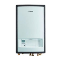
Hydraulic station
Brand:
Vaillant
| Category:
Heat Pump
| Size: 3.66 MB
Table of Contents
Table of Contents
3
1 Safety
4
Action-Related Warnings
4
General Safety Information
4
Intended Use
4
Operating Instructions
4
Control Elements
6
Design of the Product
6
Heat Pump System
6
2 Notes on the Documentation
6
Observing Other Applicable Documents
6
3 Product Description
6
Storing Documents
6
Validity of the Instructions
6
Control Panel
7
Description of the Symbols
7
Functional Description of Buttons
7
Type Designation and Serial Number
7
Basic Display
8
CE Marking
8
Fluorinated Greenhouse Gases
8
Menu Display
8
Operating Concept
8
4 Operation
8
Safety Devices
8
Starting up the Product
9
5 Care and Maintenance
10
Caring for the Product
10
Checking the Filling Pressure in the Heat Pump Circuit
10
Setting the Domestic Hot Water Temperature
10
Setting the Heating Flow Temperature
10
Switching off the Product's Functions
10
Checking the System Pressure
11
6 Troubleshooting
11
Arranging Disposal of Refrigerant
12
Guarantee
12
7 Decommissioning
11
Detecting and Eliminating Faults
11
Maintenance
11
Permanently Decommissioning the Product
11
Reading Fault Messages
11
Reading Maintenance Messages
11
8 Recycling and Disposal
11
Temporarily Decommissioning the Product
11
9 Guarantee and Customer Service
12
A Troubleshooting
13
Appendix
13
B Overview of the End User Operating Level
13
Index
15
Table of Contents
16
Installation and Maintenance Instructions
18
Action-Related Warnings
18
General Safety Information
18
Intended Use
18
1 Safety
18
Benchmark
20
Regulations (Directives, Laws, Standards)
20
Further Information
21
Heat Pump System
21
2 Notes on the Documentation 2
21
Observing Other Applicable Documents
21
3 Product Description
21
Safety Devices
21
Storing Documents
21
Validity of the Instructions
21
Cooling Mode
22
Description of the Product
22
Functions of the Heat Pump
22
Product Overview
22
Information on the Data Plate
23
Service Valve
23
Application Limits
24
CE Marking
24
Connection Symbols
24
Buffer Cylinder
25
Checking the Scope of Delivery
25
Selecting the Installation Site
25
4 Set-Up 4
25
Unpacking the Product
25
Dimensions
26
Minimum Clearances and Installation Clearances
26
Wall-Mounting the Product
26
Removing the Bottom Casing
27
Removing the Front Casing
27
Carrying out the Installation Preparations
28
Connecting the Refrigerant Pipes
28
5 Hydraulics Installation
28
Routing Refrigerant Pipes
28
Checking the Refrigerant Pipes for Tightness
29
6 Electrical Installation 6
29
Installing a Drain on the Expansion Relief Valve
29
Installing the Heating Circuit Connections
29
Installing the Heating Flow and Heating Return for the Domestic Hot Water Cylinder
29
Preparing the Electrical Installation
29
Establishing the Power Supply
30
Opening the Power Supply Pcb's Electronics Box
30
Installing Components for the Energy Supply Company Lockout Function
32
Limiting the Power Consumption
32
Menu Functions Without the Optional System Control
32
Cable Route
33
Connecting a Limit Thermostat for the Underfloor Heating
33
Installing the System Control in the Electronics Box
33
Opening the Electronics Box
33
Actuating a Circulation Pump with an Ebus Controller
34
Carrying out the Wiring
34
Connecting the Circulation Pump
34
Activating Screed Drying Without the Outdoor Unit and System Control
35
Checking the Electrical Installation
35
Connecting Cascades
35
Connecting the Domestic Hot Water Cylinder
35
Connecting the External Prioritising Diverter Valve (Optional)
35
Sealing the Power Supply PCB
35
7 Start-Up
35
Using the Additional Relays
35
Checking and Treating the Heating Water/Filling and Supplementary Water
36
Setting the Prioritising Diverter Valve
36
Filling and Purging the Heating Installation
37
Energy Balance Control
38
Purging
38
Running the Installation Assistants
38
Starting up the Product
38
Calling up Statistics
39
Calling up the Installer Level
39
Carrying out the Actuator Test
39
Compressor Hysteresis
39
Enabling the Electric Back-Up Heater
39
Purging
39
Restarting the Installation Assistants
39
Setting the Anti-Legionella Function
39
Starting up the Optional System Control
39
Using Check Programmes
39
8 Operation
40
Preventing Low Water Pressure in the Heating Circuit
40
Remaining Feed Head of the Product
40
9 Adapting the Unit to the Heating Installation
40
Checking Function and Leak-Tightness
40
Configuring the Heating Installation
40
Display of the Filling Pressure in the Heat Pump Circuit
40
Operating Concept of the Product
40
10 Troubleshooting
41
Checking Fault Codes
41
Contacting Your Service Partner
41
Displaying the Live Monitor (Current Product Status)
41
Instructing the End User
41
Querying the Fault Memory
41
Resetting Parameters to Factory Settings
41
Resetting the Fault Memory
41
Setting the Flow Temperature in Heating Mode (with no Control Connected)
41
Using Check Programmes
41
11 Inspection and Maintenance
42
Checking Maintenance Messages
42
Inspection and Maintenance Information
42
Preparing the Repair Work
42
Procuring Spare Parts
42
12 Draining
43
Checking and Correcting the Filling Pressure of the Heating Installation
43
Checking the Admission Pressure of the Expansion Vessel
43
Checking the High-Pressure Switch-Off
43
Completing Inspection and Maintenance
43
Draining the Product's Heating Circuit
43
Observing Inspection and Maintenance Intervals
43
Preparing for Inspection and Maintenance
43
13 Decommissioning
44
14 Recycling and Disposal
44
Disposing of the Product and Accessories
44
Disposing of the Refrigerant
44
Draining the Heating Installation
44
Permanently Decommissioning the Product
44
Temporarily Decommissioning the Product
44
A Wiring Diagram
45
Appendix
45
B Control PCB
46
C Basic Connection Diagram for the Energy Supply Company Lockout, Shutdown Via Connection S21
47
D Basic Connection Diagram for the Energy Supply Company Lockout, Shutdown Via Partition
48
E Installer Level Overview
49
F Status Codes
52
G Maintenance Messages
54
H Comfort Protection Mode
55
I Fault Codes
55
J 5.4 Kw Back-Up Heater
59
K 8.54 Kw Back-Up Heater at 230 V
59
L 8.54 Kw Back-Up Heater at 400 V
60
M Inspection and Maintenance Work
60
N Characteristic Values for the Temperature Sensor, Refrigeration Circuit
60
O Characteristic Values for the Internal Temperature Sensors, Hydraulic Circuit
61
P Characteristic Values for the VR10 Internal Temperature Sensors, Cylinder Temperature
62
Q Characteristic Values for the VRC DCF Outdoor Temperature Sensor
63
R Technical Data
63
S Commissioning Checklist
67
Index
70
Advertisement
Advertisement
Related Products
Vaillant aroTHERM VWL 115/2
Vaillant aroTHERM VWL 55/2 A
Vaillant aroTHERM VWL 115/2 A
Vaillant aroTHERM VWL 155/2 A
Vaillant aroCOLLECT VWL 11/4 SA
Vaillant VWL 77/5 IS
Vaillant VWL 75/5 AS
Vaillant VWL 105/5 AS S2
Vaillant VWL 125/5 AS S2
Vaillant VWL 127/5 IS
Vaillant Categories
Boiler
Water Heater
Heat Pump
Thermostat
Air Conditioner
More Vaillant Manuals
Login
Sign In
OR
Sign in with Facebook
Sign in with Google
Upload manual
Upload from disk
Upload from URL