Sign In
Upload
Manuals
Brands
UTC Fire and Security Manuals
Controller
DET-TRONICS 95-8533
UTC Fire and Security DET-TRONICS 95-8533 Manuals
Manuals and User Guides for UTC Fire and Security DET-TRONICS 95-8533. We have
1
UTC Fire and Security DET-TRONICS 95-8533 manual available for free PDF download: Instructions Manual
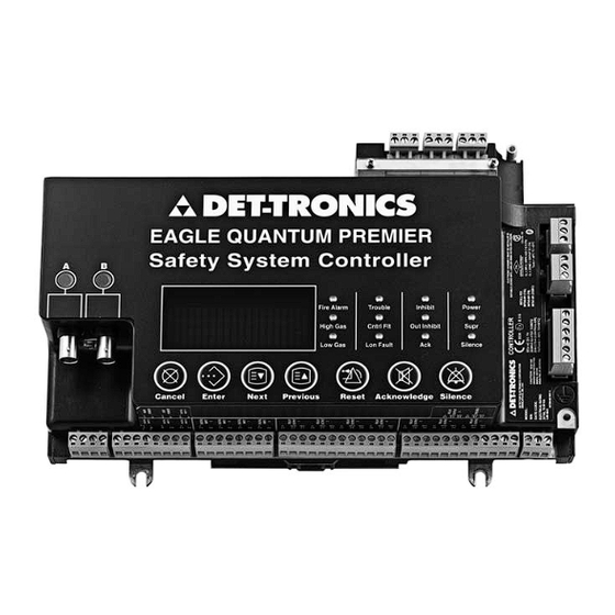
UTC Fire and Security DET-TRONICS 95-8533 Instructions Manual (146 pages)
Eagle Quantum Premier Fire and Gas Detection/Releasing System
Brand:
UTC Fire and Security
| Category:
Controller
| Size: 8 MB
Table of Contents
Table of Contents
2
Alert Messages
6
Section 1 - Safety
6
Section 2 - Introduction
7
System Description
7
Communications Loop
7
Lon Communication Heartbeat
8
Theory of Operation
8
Communication Network Fault Operation
10
Controller Logs
10
Controller User Logic
10
Multiple Wiring Faults
11
Major Component Descriptions
11
System Controller
11
Local Operating Network (Lon)
12
Network Extenders
12
Eq211Xps, Eq213Xps and Eq217Xps Power Supplies
13
Eq21Xxps Series Power Supplies and Eq2100Psm Power Supply Monitor
13
Eq2220Gfm Ground Fault Monitor
13
Field Devices
13
Flame Detectors
13
Eq3700 8 Channel DCIO Module
14
Eq3710Aim Analog Input Module
15
Eq3720 8 Channel Relay Module
15
Eq25Xxarm Agent Release Module
16
Eq3740Ipm Intelligent Protection Module
16
Eq25Xxsam Signal Audible Module
17
Eq22Xxdcu / Eq22Xxdcuex Digital Communication Units
18
Eq22Xxidc Series Initiating Device Circuit
18
Opecl Open Path Eclipse
18
Pirecl Pointwatch Eclipse
18
General Wiring Requirements
19
Identifying the Area of Protection
19
Identifying Wiring, Network (Lon), and System Power
19
Power Wiring
19
Requirements
19
Safety System Design Requirements
19
Section 3 - Installation
19
Determining Power Requirements
21
Backup Battery
23
Battery Charger
23
Eq211Xps, Eq213Xps and Eq217Xps Power Supplies
23
Eqp2120Ps(-B) Power Supplies
23
Determining Power Requirements
24
Electrostatic Discharge
25
Junction Box Grounding
25
Moisture Damage Protection
25
Response Time Vs. System Size
25
Shield Grounding
25
Ground Fault Monitor (Gfm) Installation
25
Mounting
25
Wiring
25
Network and Network Extender Installation
26
Mounting
26
Wiring
26
Initiating Device Circuit (IDC) Installation
28
Eq22Xxidc Series Initiating Device Circuit
28
Mounting
28
Wiring
28
Eq22Xxidcgf Series Initiating Device Circuit Ground Fault
29
Mounting
29
Wiring
29
Eq22Xxidcsc Series Initiating Device Circuit Short Circuit
30
Mounting
30
Wiring
30
Eq300X Controller Installation
31
Enclosure Requirements
31
Mounting
31
Serial Interface Board
31
Electrical Connections
32
Power Wiring
32
Wiring
32
Controller to Controller Communication
36
Configuration
39
Software Defined Addresses
39
Eq300X Redundant Controller Installation
39
Enclosure Requirements
39
High Speed Serial Link (Hssl)
39
Lon Wiring
39
Mounting
39
Wiring
39
Configuration
40
Controller Addresses
40
Controlnet
40
Modbus
40
S3 Configuration
40
Eq21Xxps Series Power Supply and Power Supply Monitor Installation
40
Mounting
40
Wiring
40
Measuring Battery Voltage and Charging Current
42
Startup
42
Eqp2120Ps(-B) Power Supply and Redundancy Module Installation
43
Mounting
43
Wiring
43
Startup
44
Configuration
49
Mounting
50
Wiring
50
Configuration
54
Channel Relay Module Installation
54
Mounting
54
Wiring
54
Configuration
55
Analog Input Module Installation
56
Mounting
56
Wiring
56
Configuration
57
Intelligent Protection Module Installation
58
Wiring
58
Configuration
61
Gas Detector Location and Installation
62
Environments and Substances that Affect Gas Detector Performance
62
Assembly and Wiring Procedure
63
Eq22Xxdcu Digital Communication Unit Used with Det-Tronics H2S/O2 Sensors or Other Two-Wire 4-20 Ma Devices
63
Sensor Separation for DCU with H2S and O2
64
Sensors
64
Assembly and Wiring Procedure
65
Eq22Xxdcu Digital Communication Unit Used with Pointwatch/Ductwatch
65
Sensor Separation for DCU with Pointwatch
65
Eq22Xxdcuex Digital Communication Unit (Used with Det-Tronics Combustible Gas Sensors)
66
Mounting
66
Wiring
66
Sensor Separation with Dcuex
67
Eq25Xxarm Series Agent Release Module
69
Mounting
69
Wiring
69
Address Setting
71
Eq25Xxsam Series Signal Audible Module
71
Jumpers
71
Mounting
71
Supervised Output for Deluge and Pre-Action
71
Wiring
71
Address Setting
72
Jumpers
72
System Configuration
73
Overview of Network Addresses
73
Setting Field Device Addresses
73
Typical Applications
73
Section 4 - Operation
75
Pushbuttons
75
System Controller
75
Controller Menu Options
76
Controller Status Indicators
76
Text Display
76
Controller Audible Alarm
80
Controlnet Status Indicators (Optional)
81
Sequence of Events During Aconfiguration Data Download
81
Controller Redundancy
83
Enhanced Discrete I/O Module
85
Power-Up Sequence
85
Channel DCIO Module
86
Power-Up Sequence
86
Channel Relay Module
87
Power-Up Sequence
87
Analog Input Module
88
Power-Up Sequence
88
Intelligent Protection Module
89
Embedded Logic - Control Transfer Sequence Description
89
Embedded Logic - Purpose
89
Power-Up Sequence
89
Embedded Logic - S3 Configurable Options
90
Embedded Logic - Operation
91
Eq21Xxpsm Power Supply Monitor
92
Eq2220Gfm Ground Fault Monitor
92
Eq22Xxdcu and Eq22Xxdcuex Digital Communication Units
93
Eq22Xxidc Series Initiating Device Circuit
93
Eq24Xxne Network Extender
94
Eq25Xxarm Agent Release Module
94
Eq25Xxsam Signal Audible Module
94
System Startup
95
Pre-Operation Checks
95
General Start-Up Procedures
96
Startup Procedure for Controller
97
Startup Procedure for Edio Module
97
Startup Procedure for DCIO Module
98
Section 5 - Maintenance
100
Gas Sensor Maintenance
100
Routine Maintenance
100
Batteries
100
Manual Check of Output Devices
100
O-Ring Maintenance
100
Calibration and Adjustments
101
Calibration Algorithm Afor Manual Calibration of Universal Dcu
101
Normal Calibration
101
Calibration Algorithm C for Combustible Gas Dcus and Automatic Calibration of Universal Dcus
102
Routine Calibration
102
Sensor Replacement
102
Combustible Gas
103
Initial Installation and Sensor Replacement
103
Sensor Replacement - Toxic Gas
103
Calibration Algorithm D for Universal Dcus with O2 Sensor
104
Normal Calibration
104
Sensor Replacement
104
CALIBRATION ALGORITHM GFOR Dcus with Pointwatch or Ductwatch
105
Routine Calibration
105
Sensor Replacement
105
Device Calibration Logs and Records
105
Troubleshooting
105
Appendix D - Eqp Marine, Uscg Approval
107
Appendix E - Rocker Switch Table
107
Device Repair and Return
107
Ordering Information
107
Replacement Parts
107
Eq300X Controller
110
Section 6 - Specifications
110
Lon Termination Module
111
Eq3720 Relay Module
115
Eq3710Aim Analog Input Module
116
Hart Interface Module
116
Eq3740Ipm Intelligent Protection Module
117
Eq21Xxps Power Supplies
118
Eqp2120Ps(-B) Power Supplies
119
Redundancy Module Quint-Diode/40
119
Eq2220Gfm Ground Fault Monitor
121
Eq25Xxarm Agent Release Module
122
Eq25Xxsam Signal Audible Module
122
Eq24Xxne Network Extender
123
Combustible Gas Sensor
124
Electrochemical Sensors
124
Eq21Xxps Power Supply
124
Appendix A - FM Approval Description
125
Appendix B - Csa Certification Description
133
Appendix C - Ce Mark
133
Advertisement
Advertisement
Related Products
UTC Fire and Security Det-Tronics R8471B
UTC Fire and Security DET-TRONICS 95-8522
UTC Fire and Security Det-Tronics X Series
UTC Fire and Security Det-Tronics FDRS
UTC Fire and Security Det-Tronics X220
UTC Fire and Security Det-Tronics X9800
UTC Fire and Security Det-Tronics X5200
UTC Fire and Security Det-Tronics X3301
UTC Fire and Security Det-Tronics X2200
UTC Fire and Security Det-Tronics Dual Spectrum PM-5MPX
UTC Fire and Security Categories
Control Unit
Security Sensors
Controller
Security System
Digital Camera
More UTC Fire and Security Manuals
Login
Sign In
OR
Sign in with Facebook
Sign in with Google
Upload manual
Upload from disk
Upload from URL