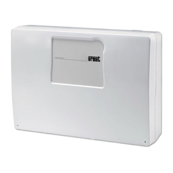
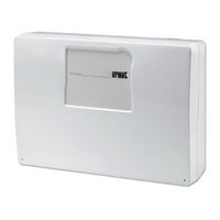
Sign In
Upload
Manuals
Brands
Urmet Manuals
Control Panel
1067/032A
Urmet 1067/032A Manuals
Manuals and User Guides for Urmet 1067/032A. We have
3
Urmet 1067/032A manuals available for free PDF download: Programming Manual, Installation Manual, Quick Start Manual
urmet domus 1067/032A Programming Manual (152 pages)
REMOTE CONTROLLABLE ALARM CONTROL PANELS
Brand:
urmet domus
| Category:
Control Panel
| Size: 1.36 MB
Table of Contents
Table of Contents
2
1 Control Devices
8
1067/022 Keypad Display
8
Function Keys
8
Leds and Status Icons
9
Zone Indications
10
Area Indications
11
1067/026 Touchscreen Keypad with Proximity Key Reader
12
Function Keys
13
Status Icons
13
Zone Indications
14
Area Indications
15
1067/334 - 1067/335 Electronic Key Readers
16
1067/434 - 1067/435 Proximity Key Reader
17
1058/035 Remote Control
18
2 System Access
19
System Access Codes
19
Default Access Codes
20
Code Change
21
How to Reset an Access Code
21
How to Enable the Hold-Up Function
22
Entering an Invalid Code or Using an Invalid Key
22
3 Menu
23
How to Access Menus
23
How to Navigate the Menus
23
Free Access Menu
24
Main Menu
25
4 System Commissioning
26
Conventions Used in Programming Procedures
26
How to Enter Alphanumeric Characters
27
Vocal Name
27
How to Enable the Installer
28
How to Enable the Technical Manager Code
28
How to Select the Language
29
LCD Info
30
How to Set Date and Time
31
Zones Programming
32
Areas Programming
34
Wired Input Programming
35
Wired Input Encoding
35
Input Types
35
Wired Input Customisation
36
Isolable
38
Ancillary Functions (Gong, Courtesy Light, Door Opener, Absence of Move)
38
Burglar Input Attributes (Release Type, and / or Zones)
38
AND Inputs
38
Programming Procedure
38
Wired Input Programming
41
Output Encoding
41
Output Types
41
Output Assignment
41
Output Customisations
41
Programming Procedure
44
Keypad Programming
46
Functions to be Configured
46
Emergency Indication
46
Programming Procedure
46
Reader Programming
48
LED Management
48
Programming Procedure
48
Keys
49
Key Acquisition
49
Delete Key
50
Key Configuration
50
Wireless Input Programming
51
Wireless Input Encoding
51
Wireless Input Types
52
Wireless Input Customisation
52
Isolable
52
Ancillary Functions (Gong, Courtesy Light, Door Opener, Absence of Move)
52
Input Attributes (Release Type, and / or Zones)
52
AND Inputs
52
Programming Procedure
52
Wireless Output Programming
55
Wireless Output Encoding
55
Wireless Output Customisation
55
Status Report
55
Programming Procedure
56
1058/035 Remote Control Programming
57
Advanced Programming
59
Remote Control System Code
59
Programming Procedure
59
General System Parameters (Timings)
60
Programming Procedure
60
Telephone Dialer
61
Telephone Numbers
61
Vocal Messages
62
SMS Text Messages
64
Alarm Sending Types
64
Alarm Message and Call Block Sending Mode
65
PSTN Parameters
69
GSM Parameters
70
GPRS Parameters
71
IDP/IP Parameters
72
PSTN Line Test
73
Period Comm Test
73
Rem Ctrl Backup
74
Answer Machine
75
Rem.ctrl Code
76
Return Call
76
Telephone Line Enabling
77
Timed Programmer
78
Operating Principles
78
Programming
79
Deleting a Command
80
System Test
80
Input Test
81
Output Test
81
Battery Test
82
Vocal Call Test
82
Alarm Receiving Centre Call Test
83
GSM Field Test
83
Environmental Listening Test
83
Radio Device Test
84
Final Tests
84
User Training
84
5 System Commissioning
85
Arming Procedure
85
Partial Arming (System with Zones Only)
86
Arming from 1067/026 Keypad
87
Partial Arming (System with Zones Only)
88
Arming with Electronic or Proximity Key
89
Total Arming from Proximity Key Reader
90
Partial Arming from Electronic Key Reader
91
Partial Arming from 1067/026 Keypad
92
Partial Arming
93
Partial Disarming (System with Zones Only)
94
Disarming from 1067/026 Keypad
95
Partial Disarming (System with Zones Only)
96
Disarming from Keypad under Hold-Up
97
Total Disarming from Proximity Key Reader
98
Partial Disarming from 1067/026 Keypad
99
Splitting
100
How to Stop Alarms in Progress
101
How to View Open Inputs
102
How to Delete the Alarms Memory
103
How to Examine the Fault and Anomaly Memory
104
6 User Remote Control
105
How to Activate Commandable Outputs at no Cost
106
List of Vocal Answer Machine DTMF Controls
107
7 Alarms, Events and Indications
108
Alarm and Event Indications
108
Description of Alarms and Indications
111
Tamper Alarm
112
Panic Indication
113
Emergency Indication
114
Detector Jamming Alarm
115
Failure Alarm from Failure Input
116
No Bus Communication Alarm
117
Description of Events
118
Door Opener Event
119
Isolated Input Event
120
Arrest System Event
121
Description of Acoustic Indications
122
8 Programming Via Computer
123
Programming Methods
123
How to Save and Restore Data on USB Flash Drive
124
How to Save Data on USB Flash Drive
125
How to Restore Data on the Control Panel
126
9 Maintenance
127
How to View Device Addresses
128
How to Upgrade Bus Device Firmware from Menu
129
Preliminary Operations
130
Firmware Upgrade at Power on
131
Control Panel Upgrade Procedure at Power on
132
Partial Reset
133
How to Interpret Viewed Data
134
How to Interpret Viewed Data
135
EN50131 Degree Compliance
136
10 Tables
137
Alarm Sending Types
138
IDP Message Structure
139
Detail of Events and Management
141
Factory Settings
142
Keys
143
Control Panel Inputs
144
Control Panel Outputs
145
Expansion Module Inputs
146
Keypad Inputs
147
Radio Expansion Module Inputs
148
Radio Expansion Module Outputs (Sirens)
149
A PSTN Communicator
150
Timed Programmer Configuration
151
Advertisement
urmet domus 1067/032A Installation Manual (120 pages)
REMOTE CONTROLLABLE ALARM CONTROL PANELS
Brand:
urmet domus
| Category:
Control Panel
| Size: 6.2 MB
Table of Contents
Table of Contents
2
Preface
6
Conformity with EN50131-1
6
Imq
7
How the Manual Is Organised
7
Conventions Used
7
Glossary
8
1 The 1067/024, 1067/032A and 1067/052A Systems
9
Main Characteristics
9
System Architecture
10
Architecture
10
Bus Data
10
Maximum System Size
11
System Connectivity
12
Connection with Remote User
13
Connection with a Remote PC
14
Connection with a Local PC
15
Connection with an Alarm Reception Centre
16
System Components
17
1067/024 Control Panel
17
1067/032A Control Panel
18
1067/052A Control Panel
19
1067/022 LCD Command Keypad
20
1067/026 Touch Screen Keypad
20
1067/008A 8-Inputs Expansion Module
21
Container for 1067/017 Expansion Module
21
1067/334 -335 Electronic Key Reader
22
1067/332 Kit Additional Keys
22
1067/434 - 435 Proximity Reader
23
1056/032 Kit Proximity Key
23
1067/092 Supplemental Power Supply with Repeater
24
1067/012A - 1067/012B Vocal Voice Synthesis Module with Handsfree Earset
24
1067/002A PSTN Communicator
25
1067/458 GSM Module
25
1067/014 Remote GSM Antenna
25
1067/015 GSM Antenna for Metallic Box (1067/052A)
26
1067/016 Cable for Keypad 1067/022
26
1067/003 USB Interface
26
1067/001 Fastpro Application Software (Rev. 2.40 or Higher)
27
1067/004 Web Server Interface
27
2 Basic Information
28
How an Intrusion Alarm System Is Made
28
The Simplest System
28
Wired, Radio, and Bus
28
Communicating with the External Environment
29
The Devices Used to Create an Alarm System
30
The Control Panel
30
The Detectors
30
The Signalling Devices
31
The Complementary Devices
32
Other Devices that Can be Integrated into the Alarm System
33
3 Design: Configuration of the Alarm System
34
Identifying the Grade of Protection
34
The Alarm System Power Supply
34
How to Design an Alarm System
35
Analysis of the Site and Needs
35
Certification Requirements
35
How to Protect Areas and People
36
The Subdivision into Zones
37
Choosing Devices
38
Positioning the System Devices
39
Tips about Installing the Radio Devices
40
Tips about the Mobile Phone Network (GSM)
41
Advanced Functions
41
The Zones and the Areas
41
Input and Output: Select the Delay to Avoid Setting off the Alarm
41
The Complementary Functions (Gong, Courtesy Light, Door Opener, Absence of Move)
43
The Attributes of the Intrusion Inputs (Release Type, and / or Zones, and Inputs)
43
Remote Activation of Commandable Outputs Free of Charge
44
Environmental Listening
44
4 Design: Calculations and Tests
45
Sizing of the Power Supplies and the Batteries
45
Battery Sizing
45
Calculation of the Total Absorption of the System
46
Using Supplementary Power Supply Units
46
Cable Sizing
46
Cables to be Used, Connections of the Shields and Installation
46
Sizing of the Power Supply Cable
47
Sizing the Power Supply and Data Transmission Bus
48
Extending the Bus with the Repeater
48
Sizing of Audio Bus
50
Sizing of Input/Output Connections
50
Control Criteria of the Mains Power Supply Voltage
50
Blackout Event
50
Continued Blackout Alarm
50
Restoration of the Mains Power Supply
50
Battery Management Criteria
50
Control and Charging of the Battery with the Mains Power Supply Present
50
Controlling the Battery with Mains Power Supply Absent
51
Test Battery
51
Self-Diagnostic Functions
51
5 Installation
52
Installation Procedure
52
Wiring
52
Preparing the 1067/024 - 1067/032A Control Panel
53
Opening the Cover
53
Openings for Cables
53
Fastening to the Wall
54
Battery Compartment and Fastening Points for the Optional Features in the 1067/024 - 1067/032A Control Panel
55
Panel
55
Assembling Expansion Modules in the 1067/024 - 1067/032A Control Panel
56
Preparing the 1067/052A Control Panel
57
Opening the Cover
57
Openings for Cables
58
Fastening to the Wall
58
Battery Compartment and Fastening Points for the Optional Features in the 1067/052A Control Panel
60
Assembling Expansion Modules in the 1067/052A Control Panel
60
Installing the 1067/024 - 1067/032A - 1067/052A Control Panels
61
Description of the Main Parts of the 1067/024 Control Panel
61
Description of the Main Parts of the 1067/032A - 1067/052A Control Panels
63
Assembly of the 1067/002A PSTN Communicator
65
Montaggio Assembly of the 1067/012A - 1067/012B Vocal Synthesis Board
66
Installation of the 1067/458 GSM Module
67
Connection of the USB Interface and Web Server
69
Temporary Connection of the 1067/003 Interface for the USB Pen Drive for Connecting to the PC
69
Installation of the 1067/004 Web Server Interface
70
Installation of the 1067/008A Expansion
71
Installation of the 1067/022 Keypad
72
Installation of the 1067/026 Touch Screen Keypad
73
5.10 Installing the Reader
75
5.11 Installation of the 1067/092 Supplementary Power Supply
75
Fastening to the Wall
75
Connecting the Power Supply and Battery
76
The 1067/092 Board
77
5.12 Connections
79
Vac Power Supply Line
79
Connecting the Data Bus
80
Connecting the Audio Bus
81
Connecting the Supplementary Power Supplies/Repeater
81
Connecting Inputs
83
Connecting Outputs
85
Connecting the Cable for KP SERVICE Keypad
87
Connecting the Telephone Dialler
87
5.13 Example of Diagram with Nc Inputs 1067/024 Control Panel
89
5.14 Example of Diagram with Double Bal. Inputs 1067/024
91
5.15 Example of Diagram with Nc Inputs 1067/032A-1067/052A
93
5.16 Example of Diagram with Double Bal. Inputs 1067/032A-1067/052A
95
6 Commissioning
97
System Power Supply
97
RUN LED Indications
97
Acquisitions of Bus Devices
98
Position of the Programming Buttons
98
Procedure for Acquiring Bus Devices
98
Using the Service Keypad
99
7 Maintenance
100
Maintenance Procedure
100
Addition and Acquisition of a New Device BUS
100
Replacing a BUS Device
100
Identifying a BUS Device
101
Interrogating a Bus Device
101
Searching for a Device
101
Deleting a BUS Device
101
Deleting a Radio Expansion
101
Acquisition / Maintenance of the Radio Devices
102
Radio Connection Test
103
Configuring Radio Parameters
104
Deleting a Radio Device
104
Resetting Factory Settings
105
Partial Reset
105
Global Reset
106
Resetting Installer, Tech. Manager, Master and User Codes
106
Resetting Hardware Installer Code and Tech. Manager Code
106
Resetting Hardware to Factory Settings
106
Resetting Devices
106
7.10 Replacing the Battery
107
7.11 Turning off the Entire System
107
7.12 Troubleshooting
108
8 Technical Specifications
111
1067/024 Control Panel
111
1067/032A Control Panel
112
1067/052A Control Panel
113
1067/022 Keypad LDC Display
114
1067/026 Keypad Touch Screen
114
1067/334 - 1067/335 Electronic Key Reader
114
8-INPUT 1067/008A Expansion Module
115
1067/012A-1067/012B Vocal Synthesis Board
115
8.10 1067/002A Pstn Communicator
115
8.11 1067/458 Gsm Module
115
8.12 1067/003 Usb Interface
116
8.13 1067/004 Web Server Interface
116
1067/092 Supplementary Power Unit with Repeater
117
urmet domus 1067/032A Quick Start Manual (12 pages)
Brand:
urmet domus
| Category:
IP Access Controllers
| Size: 0.83 MB
Advertisement
Advertisement
Related Products
urmet domus 1067/026
urmet domus 1067/022
urmet domus 1067/334
urmet domus 1067/335
urmet domus 1067/435
urmet domus 1067/434
urmet domus 1067/032
urmet domus 1067/042
Urmet 1067/024
Urmet 1067/052A
Urmet Categories
Intercom System
Security Camera
Control Unit
Security Sensors
Monitor
More Urmet Manuals
Login
Sign In
OR
Sign in with Facebook
Sign in with Google
Upload manual
Upload from disk
Upload from URL