Sign In
Upload
Manuals
Brands
UNITED IMAGING Manuals
Medical Equipment
uDR 780i
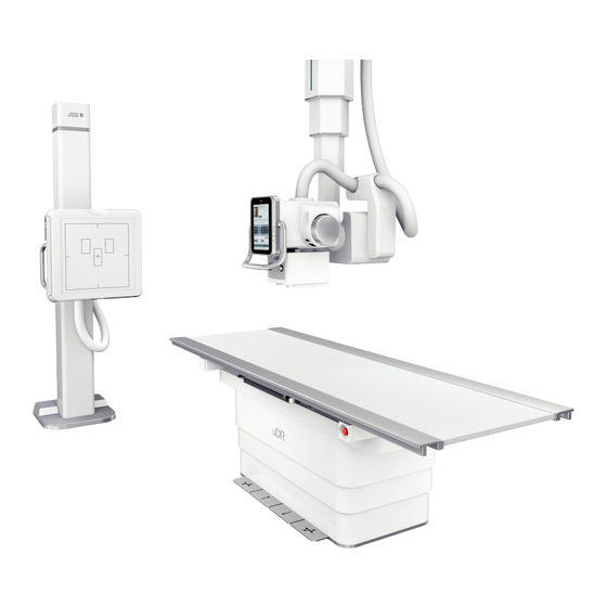
UNITED IMAGING uDR 780i Manuals
Manuals and User Guides for UNITED IMAGING uDR 780i. We have
1
UNITED IMAGING uDR 780i manual available for free PDF download: Operator's Manual
UNITED IMAGING uDR 780i Operator's Manual (202 pages)
Digital Medical X-ray Imaging System
Brand:
UNITED IMAGING
| Category:
Medical Equipment
| Size: 41 MB
Table of Contents
1 Introduction
7
Table of Contents
7
Introduction
13
About this Manual
14
Clinical Application
15
Personnel Training and Qualifications
16
Text Conventions
18
Disclaimers
19
Glossary
20
Abbreviations
22
2 Safety
25
Overview
27
Safety Level Definitions
27
Symbols and Labels
28
Table 2-1 Instruction Symbols
28
Table 2-2 Warning Symbols
29
Table 2-3 Prohibition Symbols
31
Table 2-4 Classification and Indication of Equipment
32
Table 2-5 Electricity and Electronics Safety
32
Radiation Safety
35
Radiation Protection for Patients
36
Radiation Protection for Operators
37
Electrical Safety
38
Laser Safety
40
Mechanical Safety
41
Abnormal Movement
42
Collision Protection
42
Crushing Hazards
42
Areas with Crushing Hazards
43
Figure 2-1 Dangerous Areas on the Fixed Radiographic Table
43
Figure 2-2 Dangerous Area on the X-Ray Source Assembly
43
Figure 2-3 Dangerous Collision Area on the Elevating Table
43
Figure 2-4 Dangerous Area on the Bucky Wall Stand
44
Figure 2-5 Dangerous Area on the Flat Panel Detector Tray
44
Electromagnetic Compatibility
45
Fire and Explosion Safety
46
Fire Extinguishing Agent
46
Fire Protection
46
Explosion Protection
47
Image Orientation
48
Image Quality
48
Room Lighting
48
Components in Contact with Patients
49
Patient Care
49
Safety of Patient Positioning
49
Visual Contact with the Patient
49
E-Stop Button
50
Emergency Procedures
50
Figure 2-6 E-Stop Button
50
Handling of Emergencies
50
Figure 2-10 E-Stop Buttons on the Elevating Table (2 Buttons)
51
Figure 2-7 E-Stop Button on the Control Box
51
Figure 2-8 E-Stop Button on the Bucky Wall Stand
51
Figure 2-9 E-Stop Button on the Fixed Radiographic Table
51
Emergency Power off Button
52
Battery Safety and Recycling
53
Disposal of Radioactive Wastes
53
Environment Safety
53
Equipment Compatibility
55
Service Life of the Product
56
3 System Components
57
Figure 3-1 Examples of Application Scenarios
58
System Overview
58
Components in the Scanning Room
59
Tube Ceiling Stand
59
Figure 3-2 Structure of the Tube Ceiling Stand
60
Figure 3-3 Touch User Interface
65
System Cabinet
76
Bucky Wall Stand
77
Figure 3-4 BWS Control Panels
80
Elevating Table
83
Figure 3-5 Structure of the Elevating Table
83
Fixed Radiographic Table
84
Mobile Table
85
Flat Panel Detector
86
Table 3-1 FPD Status (AS-401C)
88
Table 3-2 FPD Status (Mars1717Xu-VSI)
90
Table 3-3 Detector Battery State
92
Figure 3-6 Battery Charger for the FPD (BC-1A)
93
Figure 3-7 Battery Charger for the FPD (BC-01)
93
Ionization Chamber
96
Components in the Control Room
99
Remote Control
99
Control Box
104
Figure 3-8 Control Box (with Intercom)
104
Device Connection
107
4 System Operations
109
Inspection before System Startup
111
Logging on to the Computer System
111
Starting up the System
111
System Startup
111
Patient Preparation
113
Registering Local Patients
113
Registering Patients from RIS
113
Registration of Existing Patients
113
Adjusting System Position
115
Figure 4-1 Flat Panel Detector in Table Bucky
115
Figure 4-2 Flat Panel Detector in BWS Bucky
115
Using the Flat Panel Detector
115
TCS Movement and X-Ray Tube Assembly Positioning
116
Moving the BWS Bucky
118
Using Elevating Table
120
Figure 4-3 Coordinate Axes and Directions of Table Top Movement
122
Using Fixed Radiographic Table
122
Using Collimator
123
Using the Mobile Table
123
Grid
124
Centering
127
In the Control Room
129
In the Scanning Room
129
Patient Positioning
129
Checks before Exposure
130
Performing Exposure
131
Precautions for Exposure
131
Using the Exposure Hand Switch
131
Using the Control Box for Exposure
132
Loading Exposure Images
133
Rejecting Images
133
Restoring Images
133
Viewing Images in the Exam Interface
133
Image Post-Processing
134
Ending the Exam
135
Finishing the Exam
135
Shutting down the System
136
5 System Accessories
137
Figure 5-1 Installation on the Right (Left Figure) and Installation on the Left
138
Patient Stretch Grip of the BWS Bucky
138
Scenario
138
Installation and Removal of the Patient Stretch Grip
139
Prohibited Use
139
External Pedals
141
Stitching Stand
142
Intended Use
143
Placing the Stitching Stand
144
Specifications of the Stitching Stand
144
Adjusting the Handles of the Stitching Stand
145
Using the Base Plate of the Stitching Stand
145
Using the Step Stool
145
Grid Storage Box
147
FPD Stand
148
Diagnostic Monitor
149
Barcode Scanner
150
Parameters
150
Using the Barcode Scanner
150
6 Repair, Maintenance, and Disposal
151
Maintenance
152
Preventive Maintenance
152
Recording Results
153
Cleaning and Disinfection
154
Cleaning
155
Disinfection
156
Disposal
158
Table 6-1 List of Hazardous Materials
159
7 Technical Data
161
Equipment Classification Based on Safety Levels
162
Table 7-1 Equipment Classification Based on Safety Levels
162
Requirements for the Mains Supply
163
Table 7-2 Requirements for the Mains Supply
163
Ambient Conditions
164
Requirements for Operating Environment
164
Requirements for Transport and Storage
164
Table 7-3 Requirements for Operating Environment
164
Table 7-4 Requirements for Transport and Storage Conditions
164
Coordinate Axes and Directions
165
System Performance
165
Parameters of Component Movement
166
Parameters of Imaging Chain Components
167
Table 7-5 Maximum Output Power of the High-Voltage Generator with
168
Figure 7-1 Dimensions of the X-Ray Tube Assembly (RAD-14)
170
Figure 7-2 Dimensions of the X-Ray Tube (RAD-14)
171
Figure 7-3 Characteristics of Filament Emission
172
Figure 7-4 Maximum Rated Values (Stator Drive Frequency: 60 Hz)
173
Figure 7-5 Maximum Rated Values (Stator Drive Frequency: 180 Hz)
174
Figure 7-6 Heating and Cooling Curves of the X-Ray Tube Assembly
175
Figure 7-7 Heating and Cooling Curves of the X-Ray Tube Anode
175
Figure 7-8 Dimensions of the X-Ray Tube Assembly (RAD-60)
176
Figure 7-9 Dimensions of the X-Ray Tube (RAD-60)
176
Figure 7-10 Characteristics of Filament Emission
177
Figure 7-11 Maximum Rated Values (Stator Drive Frequency: 60 Hz)
178
Figure 7-12 Maximum Rated Values (Stator Drive Frequency: 180 Hz)
179
Figure 7-13 Heating and Cooling Curves of the X-Ray Tube Assembly
180
Figure 7-14 Heating and Cooling Curves of the X-Ray Tube Anode
180
Figure 7-15 X-Ray Tube Assembly (XRR-3331X)
181
Table 7-6 Rated Values of the Rotary Anode Motor
182
Figure 7-16 Characteristics of Filament Emission
183
Figure 7-17 Maximum Rated Values (Stator Drive Frequency: 50 Hz)
184
Figure 7-18 Heating and Cooling Curves of the X-Ray Tube Assembly
185
Figure 7-19 Heating and Cooling Curves of the X-Ray Tube Anode
185
Figure 7-20 Dimensions of the X-Ray Tube Assembly (E7254FX)
186
Figure 7-21 Characteristics of Filament Emission
187
Figure 7-22 Maximum Rated Values (Stator Drive Frequency: 60 Hz)
188
Figure 7-23 Maximum Rated Values (Stator Drive Frequency: 180 Hz)
189
Figure 7-24 Heating and Cooling Curves of the X-Ray Tube Assembly
190
Figure 7-25 Heating and Cooling Curves of the X-Ray Tube Anode
190
Table 7-8 Defective Quantum Efficiency_Mars1717Xu-VSI FPD
192
Table 7-9 Image Processing System
193
Figure 7-26 BWS Reference Axis
194
Table 7-10 Data Interfaces
194
Figure 7-27 Radiographic Table Reference Axis
195
Figure 7-28 Radiation Field Range of the Bucky Wall Stand
195
Figure 7-29 Radiation Field Range of the Table
196
Parameters of Components
197
Table 7-11 Bucky Wall Stand
197
Table 7-12 Elevating Table
197
Table 7-13 Fixed Radiographic Table
197
Table 7-14 Mobile Table
198
Index
199
Advertisement
Advertisement
Related Products
UNITED IMAGING uDR 780i Pro
UNITED IMAGING uDR 760i
UNITED IMAGING uDR
UNITED IMAGING uDR 566i-A
UNITED IMAGING uDR 566i-B
UNITED IMAGING uDR596i
UNITED IMAGING uDR 380i
UNITED IMAGING uDR 380i Pro
UNITED IMAGING Categories
Medical Equipment
More UNITED IMAGING Manuals
Login
Sign In
OR
Sign in with Facebook
Sign in with Google
Upload manual
Upload from disk
Upload from URL