Sign In
Upload
Manuals
Brands
Ultraflux Manuals
Measuring Instruments
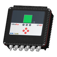
Uf 821
Ultraflux Uf 821 Manuals
Manuals and User Guides for Ultraflux Uf 821. We have
2
Ultraflux Uf 821 manuals available for free PDF download: User Manual
UltraFlux Uf 821 User Manual (109 pages)
CO & RV open channel or river
Brand:
UltraFlux
| Category:
Measuring Instruments
| Size: 4 MB
Table of Contents
Table of Contents
2
Chapter 1: Overview
4
General View of the Converter
5
Unit Closed
5
Unit Open
6
Nature of the Equipment
7
Dimensions and Weight
7
Operating Environment
7
Physical Protection
7
Power Supply
8
Communication
8
Inputs/Outputs
9
Ultrasound Chords
9
Navigation Keys
9
Operating Lights
10
Screen
10
Functions
11
Performance of the Flow Meter
11
Cleaning the Flow Meter
11
Recycling the Flow Meter
12
CE Marking
12
Chapter 2: Safety Instructions
13
Using the Flow Meter
14
Equipment Connected to the Flow Meter
15
Symbols Used on the Flow Meter
15
Maintenance Work on the Flow Meter
16
Contact Address
17
Chapter 3: Installation and Wiring
18
General
19
Wall Mounting and Space Requirement
19
Using the Cabinet
20
Using the Lid Stay
21
Tool-Free Removal of the Lid
21
Wiring Instructions
22
Connection to the Protective Ground (to be Carried out First)
22
Wiring the Terminals
22
Power Supply
22
Ultrasonic Chords
23
Input/Output Terminals
24
Wiring of the Current Output Modules
25
Wiring of the Current Input Modules
25
Wiring of the Voltage Input Modules
25
Wiring of the Relay Modules
25
Wiring of the Temperature Modules
26
Communication Terminal Board
26
USB Connection
27
Chapter 4: Implementing a Measuring Point
28
Choosing the Measurement Location
29
Installing the Probes
29
Measurements to be Taken on Site
30
Analysing and Processing Data Measured on Site
30
Topography of the Site
30
Determining the Different Levels in Relation to the Stream
30
Transferring the Data Collected to the Converter
31
CHAPTER 5: USING and CONFIGURING the Uf 821
32
Using the Uf 821
33
Operating Mode
33
Keypad
34
Leds
35
Main Configuration Elements
36
Geometric and Physical Definition of the Measuring Point
36
Composition of a Measuring Point
36
Reference Systems Used
36
Definition of the Reference Planes
36
Correspondence between Customer Reference System and Section Description Reference System
38
Number of Channels
38
Configuring the Uf 821
39
Flow Meter Menu
39
SIMPLE Configuration Mode
40
Configuration" Menu
40
Option Files" Window
40
Reset
40
Confirmation (of Reset)
40
Settings
41
Menu
41
Access Code
41
Language
41
Station Name
41
Back Light
42
Connection
42
Time Delay before Return to "Measurement" Mode
42
Pipe/Fluid Settings" Menu
43
Number of Chords
43
Flow Unit (Unit Q)
43
Flow Graph
43
Type of Fluid
43
Chord Settings
43
Section Description" Menu
44
Section Description
44
Gauge Offset
44
Surface S0
44
Level Settings" Menu
45
Number of Level Measurements
45
Hydraulic Profile" Menu
45
Description of the Hydraulic Profile
45
Choosing the Definition Mode of the Hydraulic Profile
47
Absolute Mode
47
Relative Mode
48
Height/Velocity Settings" Menu
48
Velocity Profile in Low Water Situation
48
Totalizer Settings" Menu (if Activated)
50
Activation and Direction of Metering
50
Pulse Unit and Weight
50
Resetting a Totalizer (if Authorised)
50
Input/Output Settings" Menu (if Activated)
51
Current Input and Voltage Input Module
51
Temperature Input Module
52
Contact Input Module
52
Current/Voltage Output Module
52
Relay Output Module
53
Logger Settings" Menu (if Activated)
55
Resetting the Logger
55
Confirming Logger Reset
55
Number of Logger Parameters
55
Logger Mode
55
Logger Increments
55
Logger Autonomy
55
Logger Variables
56
Logger on Variation
56
Echo Display" Menu
57
NORMAL Configuration Mode
58
Pipe/Fluid Settings" Menu
58
Memory
58
Filter
59
Deletion Rate (Cutoff Q)
60
Product
60
Delta T0
60
Vmin and Vmax
60
Probe Immersion Depth
60
ADVANCED Configuration
61
Pipe/Fluid Settings" Menu
61
Delta V Filtering
61
Weighting Coefficients of the Chords
61
Required Gain and Maximum Gain
61
Linearization Settings" Menu
62
Advanced Configuration" Menu
62
Simulation Mode
62
Special Probes
63
US & TRT Processing
63
Firmware Update" Menu
63
Measurement" Mode
64
Available Pages
64
Flow Rate
64
Channel Measurement
64
Specific Information Relating to the Chords
64
Totalizers
65
Date and Time
65
Logger Info
65
Events
65
Probe Type
66
Flow Graph
66
Verification of Measurement Quality and Consistency
66
Chapter 6: Function Engine
67
Principle
68
Application Example
68
Water Temperature Calculation
68
Chapter 7: Pc Software
69
Introduction
70
Installing and Running the Software
70
Connecting the Flow Meter to the PC
71
Home Page
71
Options Window
72
Icons
72
File Menu
73
Measurement Window
73
List of Available Tabs
73
General" Tab
74
QA" Tab (Flow Rate)
75
Input-Output" Tab
76
Settings Window
76
List of Available Tabs
76
General" Tab (in the "General" Drop-Down Menu)
77
Logger" Tab (in the "General" Drop-Down Menu)
78
Totalizers" Tab (in the "General" Drop-Down Menu)
78
Inputs/Outputs" Tab (in the "General" Drop-Down Menu)
79
Channel" Tab (in the "Channel" Drop-Down Menu)
80
Chord" Tab (in the "Channel" Drop-Down Menu)
80
Section" Tab (in the "Channel" Drop-Down Menu)
81
Hydraulic Profile" Tab (in the "Channel" Drop-Down Menu)
82
Level" Tab (in the "Channel" Drop-Down Menu)
82
Height/Velocity" Tab (in the "Channel" Drop-Down Menu)
83
Linearisation" Tab (in the "Channel" Drop-Down Menu)
83
Archiving, Processing and Printing of Saved Files
84
Settings Files
84
Appendix I: Characteristic Echo Signals
85
Appendix II: Speed of Sound in Water
88
Appendix III Troubleshooting
90
III.1 Diagnostic Indications
91
III.2 Description of Fault Bits
93
III.3 Fault Grid
96
Appendix IV: Link Protocol of the Uf 821
97
IV.1 Serial Link Characteristics
98
IV.2 Reading of N Words (with N ≤ 125)
99
IV.3 Modbus / Jbus Table
100
IV.4 CRC16 Calculation Algorithm
104
Advertisement
Ultraflux Uf 821 User Manual (107 pages)
Brand:
Ultraflux
| Category:
Measuring Instruments
| Size: 4 MB
Table of Contents
Table of Contents
2
Chapter 1: Overview
4
General View of the Converter
5
Unit Closed
5
Unit Open
6
Nature of the Equipment
7
Dimensions and Weight
7
Operating Environment
7
Physical Protection
7
Power Supply
8
Communication
8
Inputs/Outputs
9
Ultrasound Chords
9
Navigation Keys
9
Operating Lights
10
Screen
10
Functions
11
Performance of the Flow Meter
11
Cleaning the Flow Meter
11
Recycling the Flow Meter
12
CE Marking
12
Chapter 2: Safety Instructions
13
Using the Flow Meter
14
Equipment Connected to the Flow Meter
15
Symbols Used on the Flow Meter
15
Maintenance Work on the Flow Meter
16
Contact Address
17
Chapter 3: Installation and Wiring
18
General
19
Wall Mounting and Space Requirement
19
Using the Cabinet
20
Using the Lid Stay
21
Tool-Free Removal of the Lid
21
Wiring Instructions
22
Connection to the Protective Ground (to be Carried out First)
22
Wiring the Terminals
22
Alimentation
22
Ultrasonic Chords
23
Input/Output Terminals
24
Wiring of the Current Output Modules
25
Wiring of the Current Input Modules
25
Wiring of the Voltage Input Modules
25
Wiring of the Relay Modules
25
Wiring of the Temperature Modules
26
Communication Terminal Board
26
USB Connection
27
Chapter 4: Installing a Measuring Point
28
Composition of a Measuring Point
29
Choosing the Measurement Location
29
Straight Lengths to be Used
29
Monochord Measurement
29
Multichord Measurement
31
Choosing the Probe Location
33
Installing Probes and Connectors
35
Permanent External (Clamp-On) Probes
35
Preparing the Pipe
35
Installing the Elastomer Strip
35
Installing the Probe
35
Temporary External (Clamp-On) Probes
35
Selecting and Installing the Coupling Medium
35
Installing the Probe
36
Inserted Probes
36
Flanged Probes
36
Screw Probes
37
Probes with Air Lock
37
CHAPTER 5: USING and CONFIGURING the Uf 821
38
Using the Uf 821
39
Operating Mode
39
Keypad
40
Leds
41
Main Configuration Elements
42
Configuring the Uf 821
42
Number of Channels
42
Description of the Pipe
42
Flow Meter Menu ("Settings" Mode)
43
SIMPLE Configuration
44
Configuration" Menu
44
Config. Files" Window
44
Reinitialisation
44
Confirmation (of Reinitialisation)
44
Configuration
45
Menus
45
Access Code
45
Language
45
Station Name
45
Back Light
46
Link
46
Timer before Return to "Measurement" Mode
46
Pipe/Fluid Configuration" Menu
46
Number of Chords
46
Flow Rate Unit (Q Unit)
46
Flow Graph
46
Chord Settings
47
Type of Fluid
47
Definition of the Pipe
47
Totalizer Configuration" Menu (if Enabled)
48
Activation and Counting Direction
48
Pulse Unit and Weight
48
Resetting a Totalizer (if Authorised)
48
Inputs/Outputs" Menu (if Enabled)
49
Current Input and Voltage Input Module
49
Temperature Input Module
50
Contact Input Module
50
Current/Voltage Output Module
50
Relay Output Module
51
Logger Settings" Menu (if Enabled)
53
Resetting the Logger
53
Confirmation of Resetting the Logger
53
Number of Parameters for the Logger
53
Logger Mode
53
Logger Interval
53
Logger Autonomy
53
Logger Variables
54
Log on Variation
54
Echo Display" Menu
55
NORMAL Configuration
56
Pipe/Fluid Configuration" Menu
56
Memory
56
Filter
57
Delta T0 and Auto Zero
58
C0 and Delta C
58
Deletion Rate (Qeff)
59
ADVANCED Configuration
60
Pipe/Fluid Configuration" Menu
60
Delta V Filtering
60
Material of the Pipe Wall
60
Laminar/Turbulent Transition
61
Seek Gain and Gain Max
61
Weighting Coefficients of the Chords
62
Linearisation Settings" Menu
62
Advanced Settings" Menu
63
Simulation Mode
63
Special Probes
63
US & TRT Processing
63
Firmware Update" Menu
63
Measurement" Mode
64
Pages Available
64
Flow
64
Pipe Measurements
64
Specific Information Relating to the Chords
64
Totalizers
65
Date and Time
65
Info Logger
65
Events
65
Distance between Probes
66
Flow Graph
66
Verification of the Quality and Consistency of the Measurement
66
Chapter 6: Function Engine
67
Principle
68
Application Example: Calorimetry
68
Water Temperature Calculation
68
Calorimetry
68
Chapter 7: Pc Software
70
Introduction
71
Installing and Running the Software
71
Connecting the Flow Meter to the PC
72
Home Page
72
Configuration Window
73
Icons
73
File Menu
74
Measurement Window
74
List of Available Tabs
74
General" Tab
75
QA" Tab (Flow Rate)
76
Inputs/Outputs" Tab
77
Settings Window
77
List of Available Tabs
77
General" Tab (in the "General" Drop-Down Menu)
78
Logger" Tab (in the "General" Drop-Down Menu)
79
Totalizers" Tab (in the "General" Drop-Down Menu)
79
Inputs/Outputs" Tab (in the "General" Drop-Down Menu)
80
Pipe" Tab (in the "Pipe" Drop-Down Menu)
81
Definition of Chords" Tab (in the "Pipe" Drop-Down Menu)
81
Linearization" Tab (in the "Pipe" Drop-Down Menu)
82
Archiving, Processing and Printing of Saved Files
83
Settings Files
83
Appendix I: Characteristic Echo Signals
84
Appendix II: Speed of Sound in Water
87
Appendix III Troubleshooting
89
III.1 Diagnostic Indications
90
III.2 Description of Fault Bits
92
III.3 Fault Grid
95
Appendix IV: Link Protocol of the Uf 821
96
IV.1 Serial Link Characteristics
97
IV.2 Reading of N Words (with N ≤ 125)
98
IV.3 Modbus / Jbus Table
99
IV.4 CRC16 Calculation Algorithm
103
Advertisement
Related Products
UltraFlux UF 801-PB
UltraFlux UF 801-P
UltraFlux UF 831
Ultraflux Uf 841
Ultraflux Uf 811
Ultraflux Uf 811 CO
Ultraflux Minisonic 2000
UltraFlux Minisonic 2000 dual chord
Ultraflux Minisonic 600
UltraFlux Minisonic 600 dual chord
Ultraflux Categories
Measuring Instruments
Security Sensors
More Ultraflux Manuals
Login
Sign In
OR
Sign in with Facebook
Sign in with Google
Upload manual
Upload from disk
Upload from URL