Sign In
Upload
Manuals
Brands
U.S. Boiler Company Manuals
Boiler
K2FTC-155
U.S. Boiler Company K2FTC-155 Manuals
Manuals and User Guides for U.S. Boiler Company K2FTC-155. We have
1
U.S. Boiler Company K2FTC-155 manual available for free PDF download: Installation, Operating And Service Instructions
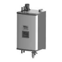
U.S. Boiler Company K2FTC-155 Installation, Operating And Service Instructions (177 pages)
CONDENSING HIGH EFFICIENCY DIRECT VENT GAS - FIRED HOT WATER BOILER
Brand:
U.S. Boiler Company
| Category:
Boiler
| Size: 13.23 MB
Table of Contents
Safety Information
2
Table of Contents
6
General Configuration
7
Product Description
7
Product View
7
Specifications
7
Boiler Internal Component Locations
8
III. before Installing
9
Vent Lengths
9
Locating the Boiler
10
Minimum Clearances to Combustible Construction
11
Mounting the Boiler
12
Wall Mounting
12
Dimensions
13
Boiler Mounting Bracket Installation / Boiler Wall Mounting
14
Air for Ventilation
15
Vent System Design
16
VII. Venting
16
Horizontal Twin Pipe
17
Vertical Twin Pipe
17
Split Venting
17
Listed Vent Systems and Materials
18
Maximum Vent and Air Intake Lengths
18
Clearances to Combustibles
19
Pitch of Horizontal Vent Piping
19
Vent/ Air Intake Fitting Equivalent Length
19
Supporting Pipe
20
Allowing for Thermal Expansion
20
Running PVC Vent Pipe Inside Enclosures and through Walls
20
Vent Manufacturer’s Instructions
20
Expansion Loops for CPVC/PVC Pipe
21
Wall Penetration Clearances for PVC Vent Pipe
21
Design Requirements Unique to Horizontal Twin Pipe Venting Systems
22
Summary of Horizontal Twin Pipe Venting Options
23
Horizontal Vent and Air Intake Terminal Location
24
Horizontal CPVC/PVC Venting with Low Profile Terminal
25
Horizontal CPVC/PVC Venting with Concentric Vent Terminal
25
Duravent, Selkirk, Polyflue, Centrotherm Innoflue Horizontal Venting
26
Duravent Polypro Horizontal Venting with Concentric Terminal
26
Location of Vent Terminals
27
Design Requirements Unique to Vertical Venting Systems
28
Snorkel Terminal Configuration
28
Permitted Terminals for Vertical Venting
28
Ipex FGV Concentric Terminal
28
Summary of Vertical Twin Pipe Venting Options
29
Summary of Vertical “B-Vent Air Chase” Vent Options
30
Vertical Vent and Air Intake Location
31
Requirements for B-Vent Air Chase Options
31
Equivalent Length of Flex Pipe
32
Vertical CPVC/PVC Venting
33
Vertical CPVC/PVC Venting with IPEX Concentric Vent Terminal
33
Vertical Single Wall PP Venting
34
Duravent Polypro Vertical Venting with Concentric Terminal
34
Duravent Polypro B-Vent Air Chase System
35
Centrotherm Innoflue B-Vent Air Chase System
35
Design Requirements Unique to Split Vent Systems
36
Permitted Terminals for Split Venting
36
Vent Terminal Location/Horizontal Air Intake Terminal Location
36
Use of Abandoned Chimneys as a Vent Chase
36
Summary of Split Vent System Options
38
Split Rigid Vent System
40
Split Vent System (Flex in B-Vent Chase)
40
Split Vent System (Flex in Abandoned Masonry Chimney)
41
Masonry Chimney Chase Requirements
42
Assembly of CPVC/PVC Vent Systems
43
Assemble the Vent System, Starting at the Boiler
43
Installation of Air Intake System
44
Installation of Horizontal Fitting Terminals
44
Vent Connections and Flue Gas Sample Cap Location
44
Installation of Standard Horizontal Terminals
45
Installation of Standard Vertical Terminals
45
Installation of Vertical Fitting Terminals
46
Installation of IPEX Low Profile Vent Terminal
46
Installation of Diversitech Low Profile Terminal
46
Installation of IPEX FGV or Diversitech CVENT Concentric Vent Terminal
46
Installation of IPEX Low Profile Terminal through Sidewall
47
Installation of Diversitech Low Profile Terminal through Sidewall
47
Cutting IPEX and Diversitech Concentric Vent Terminals
48
Installation of Ipex/Diversitech Concentric Terminal through Sidewall
48
Installation of IPEX and Diversitech Concentric Terminal through Roof
49
Assembly of Duravent Polypro Vent Systems
50
Polypro Locking Band Installation
50
Installation of Duravent Polypro Horizontal Concentric Vent Terminal
53
Vertical Installations Using Polypro Vertical Concentric Termination
53
Cutting Duravent Polypro Horizontal Concentric Vent Terminal
53
Install Duravent Polypro Concentric Vent Terminal through Sidewall
54
Installation of Duravent Polypro Concentric Terminal through Roof
54
Assembly of Selkirk Polyflue Vent Systems
55
Installations Using Polypro-Flex
55
Installations Using Flexible Polyflue
57
Polyflue Pipe Locking Band Installation
57
Assembly of Centrotherm Innoflue Vent Systems
59
Innoflue Connector Ring Installation
59
Condensate Trap and Drain
62
Installations Using Innoflue Flex
62
Condensate Trap Installation
63
Removing an Existing Boiler from a Common Chimney
64
Gas Piping
65
VIII. Gas Piping
65
Gas Connection to Boiler
66
Minimum and Maximum Inlet Pressures
66
General System Piping Precaution
67
IX. System Piping
67
Non-Metallic Tubing
67
Water Quality and Boiler Water Additives
67
Standard Piping Installation Requirements
68
Near Boiler Piping
69
Flow Limitations
70
Near Boiler Piping Design
70
Boiler Head Loss
71
Primary/Secondary Piping
71
Fitting and Valve Equivalent Length
73
Hydraulic Separators
73
Indirect Water Heater Loop Piping
73
Near Boiler Piping; Heating Only
74
Near Boiler Piping - Heating Plus Supply Piped Indirect Heater
75
Near Boiler Piping - Heating Only
77
Method 2: Direct Connection to Heating System
80
Air Handlers
81
Piping for Special Situations
81
Piping with a Chiller
81
Systems Containing Oxygen
81
Line Voltage (120 VAC) Field Connections
82
Wiring
82
Low Voltage Field Connections
83
High Voltage PCB Terminal Connections
84
Low Voltage PCB Terminal Connections
84
Alarm Contacts
85
External Limit
85
Header Sensor
85
Outdoor Sensor
85
Prope Installation of Header Sensor
86
Internal Wiring Ladder Diagram
87
Internal Wiring Connections Diagram
89
TACO SR504 or Equivalent Zone Panel Wiring Connection Diagram
90
Sage Zone Control Circulator Panel Wiring Diagram
91
Start-Up and Checkout
92
Burner Flame
95
Gas Valve Detail
96
Acceptable Combustion Readings for Natural Gas
97
Starting Number of Throttle Turns for Natural Gas
97
Operating Instructions
98
To Turn off Gas to Appliance
98
What to Do if You Smell Gas
98
Advanced Modulating Control
99
Advanced Touch Screen Display
99
Built-In Safety Control
99
Controller
99
Operation
99
XII. Operation
99
Circulator Control
100
Multiple Boiler Sequencer Peer-To-Peer Network
100
Supply Water Temperature Regulation
100
Warm Weather Shutdown (WWSD)
100
Boiler Protection Features
101
High Differential Temperature Limit
101
Outdoor Air Reset
101
Supply Water Temperature High Limit
101
Boiler Mounted Limit Devices
102
Ignition Failure
102
Multiple Boiler Control Sequencer
102
Stack High Limit
102
Advanced Boiler Sequencing
103
Customized Sequences
103
Innovative Condensing Boiler Control
103
Optimized Boiler Modulation
103
Boiler Sequence of Operation
104
Normal Operation
104
Home Screen Details
105
Screen Navigation
105
Using the Display
105
Status Screens
106
Detail Screens
108
Zone Control Status Screens
108
Multiple Boiler Sequencer Screens
109
Adjust Mode Screens
110
Adjusting Parameters
110
Changing Adjustable Parameters
110
Entering Adjust Mode
110
Parameters Changed Using the Boiler Type Parameter Selections
113
Expected Heat Rate Adjustment (with Zone Control Connected)
114
Expected Heat Rate Adjustment Screens (Heatmatch Software)
114
Example Pump Parameter Selections
116
Single Boiler Indirect Water Heater (IWH) Piped to Primary
116
Single Boiler with no Indirect Water Heater
116
Single Boiler with Supply Piped IWH, System and DHW Wired to Master
117
Multiple Boilers IWH Piped to Primary, Domestic Hot Water Priority
118
Multiple Boilers, IWH Piped to Primary
118
Outdoor Reset Curve
125
Important Product Safety Information
128
Service and Maintenance
128
Annual Inspections and Service
130
Monthly Inspections
130
Disconnecting Flexible Gas Line
131
Igniter and Flame Sensor Location
131
Condensate Trap Exploded Parts View
133
Igniter Gap
133
Display Faults
135
Problems Where no Error Code Is Displayed
135
XIV. Troubleshooting
135
Help Screen Diagnostic Features
136
Help Screen Faults
136
Active Fault Screen Faults
137
Lockout Condition
138
Troubleshooting Problems Where a Soft Lockout Code Is Displayed
138
Troubleshooting Problems Where a Hard Lockout Code Is Displayed
140
XV. Repair Parts
141
Exploded Views and Parts Lists
142
Instructions for Conversion of this Boiler for Use with LP Gas
156
LP Gas (Propane) Orifice Sizes (Field Installed)
156
LP Orifice Installation
156
Starting Number of Throttle Turns for Conversion to LP Gas
158
Acceptable Combustion Readings for LP Operation
159
Adjusting Boiler Type
160
Altitude Start-Up Instructions for Natural Gas and LP
160
Appendix A: LP Gas Conversion Instructions
160
Appendix B: Instructions for High Altitude Installation above 4,500 Ft
160
Gas Valve Detail (High Altitude Only)
161
Acceptable Combustion Readings (above 4500 Ft.)
162
Altitude Adjustments (above 4500 Ft. Only)
162
Fan Speeds Tested
163
Appendix C: K2FTC-155 Combi Instruction Manual
164
Combi Piping Assembly Outside of Jacket
167
Domestic and Space Heating Piping Diagram for K2FTC-155
168
DHW Assembly Diagram
169
DHW Section (at Boiler)
170
Electrical
170
System Readiness
170
Boiler Control Set-Up
171
Mixing Valve Set-Up
171
Flat Plate Heat Exchanger Replacement
172
Domestic Actuator Replacement
173
Appendix D: Special Requirements for Side-Wall Vented Appliances in the Commonwealth of Massachusetts
174
Advertisement
Advertisement
Related Products
U.S. Boiler Company K2FT-110
U.S. Boiler Company K2FT-085
U.S. Boiler Company K2FT-270
U.S. Boiler Company K2FT-205
U.S. Boiler Company K2FT-155
U.S. Boiler Company K2WT-120B
U.S. Boiler Company K2WT-150B
U.S. Boiler Company K2WT-180B
U.S. Boiler Company K2WT-180M
U.S. Boiler Company K2WT-100B
U.S. Boiler Company Categories
Boiler
Water Heater
Boiler Supplies
Monitor
Adapter
More U.S. Boiler Company Manuals
Login
Sign In
OR
Sign in with Facebook
Sign in with Google
Upload manual
Upload from disk
Upload from URL