Sign In
Upload
Manuals
Brands
turck Manuals
Gateway
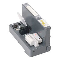
BL20-GWBR-CANOPEN
turck BL20-GWBR-CANOPEN Manuals
Manuals and User Guides for turck BL20-GWBR-CANOPEN. We have
1
turck BL20-GWBR-CANOPEN manual available for free PDF download: User Manual
turck BL20-GWBR-CANOPEN User Manual (95 pages)
BL20 series FOR CANopen
Brand:
turck
| Category:
Gateway
| Size: 3 MB
Table of Contents
Table of Contents
5
1 About this Manual
9
Documentation Concept
10
Description of Symbols Used
11
Overview
12
Prescribed Use
12
Notes Concerning Planning /Installation of this Product
12
List of Revisions
13
2 BL20 Philosophy
15
The Basic Concept
16
BL20 Components
17
Gateways
17
Power Distribution Modules
17
Gateways with Integrated Power Supply
17
Gateways Without Power Supply
17
Electronics Modules
18
Base Modules
19
End Plate
21
End Bracket
21
Jumpers
22
Marking Material
22
Shield Connection, 2-Pole for Analog Modules
23
3 Short Description of Canopen
25
Canopen
26
General
26
Communication
27
Network Management Messages
27
Service Data Objects (Sdos)
27
Process Data Objects (Pdos)
28
Special Function Objects
28
BL20 and Canopen
29
Electronic Data Sheet - EDS File
30
4 BL20 - Gateway for Canopen
31
Introduction
32
Function
33
Technical Information
34
Technical Data
35
General Technical Data
35
Relating to a Station
35
Approvals
37
Base Modules
37
Structure Diagram of a Gateway
38
Technical Data BL20-GW-CANOPEN
38
Technical Data BL20-GWBR-CANOPEN
39
Connections for Data Cables to BL20-GW-CANOPEN
40
Fieldbus Connection Via SUB-D Socket
40
Fieldbus Connection through Direct Wiring
40
Connections of the Data Cables to BL20-GWBR-Canopen
42
Fieldbus Connection Via Open Style Connector
42
Service Interface Connection
44
Connection with I/O-ASSISTANT-Connection Cable
44
Setting the Bit Transfer Rate through DIP-Switches
45
Node-ID Setting
47
Acceptance of the BL20 Station Configuration
49
Status Indicators/ Diagnostic Messages Gateway
50
4.10.1 Diagnostic Messages Via Leds
50
5 BL20 - Communication in Canopen
53
6 Guidelines for Station Planning
55
Random Module Arrangement
56
Complete Planning
56
Maximum System Extension
56
Power Supply
58
Gateway Supply
58
Module Bus Refreshing
58
Creating Potential Groups
62
Protecting the Service Interface on the Gateway
62
C-Rail (Cross Connection)
63
Direct Wiring of Relay Modules
64
Plugging and Pulling Electronics Modules
65
Extending an Existing Station
66
Firmware Download
67
7 Guidelines for Electrical Installation
69
General Notes
70
General
70
Cable Routing
70
Cable Routing Inside and Outside of Cabinets
70
Cable Routing Outside Buildings
70
Lightning Protection
71
Transmission Cables
71
Cable Types
71
Potential Relationships
72
General
72
Potential-Free Installation
72
Non-Isolated Installation
72
Electromagnetic Compatibility (EMC)
73
Ensuring Electromagnetic Compatibility
73
Grounding of Inactive Metal Components
73
PE Connection
73
Earth-Free Operation
73
Mounting Rails
74
Protect against High Frequency Interference Signals
74
EMC Compliant Cabinet Installation
75
Shielding of Cables
76
Potential Compensation
77
Switching Inductive Loads
78
Protection against Electrostatic Discharge (ESD)
78
Bus Connection
79
Two-Pole Shield Connection
80
8 BL20-Approvals for Zone 2/ Division
81
Advertisement
Advertisement
Related Products
turck BL20-GW-CANOPEN
turck BL20
turck BL20-4DI-24VDC-P
turck BL20-4DI-24VDC-N
turck BL20-E-8DI-24VDC-P
turck BL20-2DO-120/230VAC-0.5A
turck BL20-E-8DO-24VDC-0.5A-P
turck BL20-2AO-I
turck BL20-1RS232
turck BL20-E-1SWIRE
turck Categories
Accessories
Security Sensors
I/O Systems
Control Unit
Measuring Instruments
More turck Manuals
Login
Sign In
OR
Sign in with Facebook
Sign in with Google
Upload manual
Upload from disk
Upload from URL