Sign In
Upload
Manuals
Brands
Triumph Manuals
Motorcycle
Trident T150R
Triumph Trident T150R Manuals
Manuals and User Guides for Triumph Trident T150R. We have
1
Triumph Trident T150R manual available for free PDF download: Workshop Manual
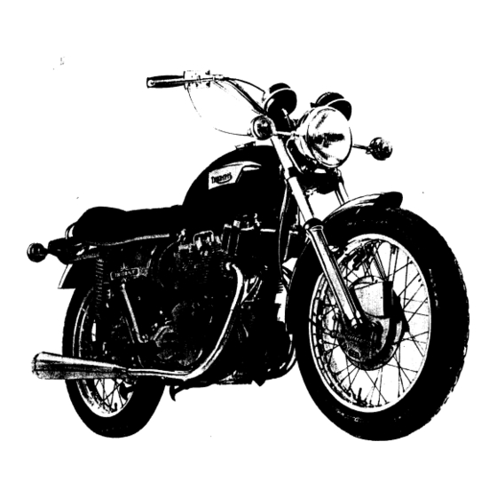
Triumph Trident T150R Workshop Manual (198 pages)
Brand:
Triumph
| Category:
Motorcycle
| Size: 18.19 MB
Table of Contents
Engine and Frame Numbers
3
Factory Service Arrangements
4
Replacement Parts
4
Repairs
4
Service Exchange Reconditioned Units
4
Contents
7
General Data
9
Gearbox
12
Frame and Attachment Details
14
Wheels, Brakes and Tyres
14
Front Forks
14
Lubrication System
17
Routine Maintenance
18
Guide to Lubrication Points
19
Engine Lubrication Diagram
20
Recommended Lubricants
21
Approved Lubricants
21
Engine Lubrication System
22
Changing the Engine Oil and Cleaning the Filters
22
Crankcase Sump Filter
22
Tappet Oil Feed from Central Main Bearings
23
Tappet Oil Feed through Cylinder Block
23
Oil Pressure
24
Underside View of Engine/Gearbox Unit
24
Stripping and Reassembling the Oil Pressure Release Valve
25
Exploded Oil Pressure Release Valve
25
Removing and Replacing the Oil Pump
26
Removing and Refitting the Oil Cooler
26
Exploded Oil Pump
26
Removing and Replacing the Rocker Oil Feed Pipe
27
Oil Cooler Mountings
27
Anti-Drain Valve
28
Contact Breaker Lubrication
28
Gearbox Lubrication
29
Primary Chaincase Lubrication
29
Rear Chain Lubrication and Maintenance
30
Section through the Primary Chaincase
30
Greasing the Steering Head Ball Races
31
Wheel Bearing Lubrication
31
Rear Chain Oil Feed Adjustment
31
Telescopic Fork Lubrication
32
Lubrication Nipples
32
Swinging Fork Pivot
32
Swinging Fork Pivot Lubrication Nipple
32
Lubricating the Control Cables
33
Speedometer and Tachometer Cable Lubrication
33
Brake Pedal Spindle Lubrication
33
Engine
34
Exploded View of 750 C.C. Engine/Gearbox Unit
35
Description
36
Removing and Replacing the Engine Unit
37
Location of Engine Lifting Bars
38
Removing and Replacing Rocker Boxes
39
Inspecting the Pushrods
40
Stripping and Reassembling the Rocker Boxes
41
Refitting Rocker Spindle Using Service Tool D2221
41
Inlet
42
Exhaust
42
Adjusting the Valve Rocker Clearances
43
Position of Camshaft for Valve Setting
43
Removing and Replacing the Air Cleaner
44
Carburetor Description
44
Exploded View of Carburetor
45
Removing and Replacing the Carburetors
46
Inlet Manifold Assembly
46
Stripping and Reassembling the Carburetors
47
Inspecting the Carburetor Components
47
Resetting the Carburetors
48
Synchronizing the Throttle Slides
48
Removing and Refitting the Cylinder Head Assembly
49
Cylinder Head Bolt Tightening Sequence
49
Removing and Refitting the Valves
50
Renewing the Valve Guides
50
Valve Components
50
Decarbonizing
51
Re-Seating the Valves
51
Valve Seating Tools
52
Cutting a Valve Seat
52
Removing and Replacing the Cylinder Block and Tappets
53
Protecting the Con. Rods
53
Position of Cam Followers
53
Inspecting the Cam Followers
54
Inspecting the Tappet Guide Blocks
54
Removing and Refitting the Pistons
55
Removing and Replacing the Piston Rings
56
Inspecting the Pistons and Cylinder Bores
56
Refitting a Tapered Piston Ring
56
Table of Suitable Rebore Sizes
57
Removing and Replacing the Contact Breaker
57
Cylinder Bores
57
Adjusting the Contact Breaker Points
58
Contact Breakers, 7CA
58
Re-Setting the Ignition Timing
59
Static Timing
59
Showing Location Tool in Use
59
Locking the Auto Advance Mechanism
59
Ignition Timing Using a Stroboscope
60
Removing and Refitting the Timing Cover
60
Timing Mark on the Rotor
60
Extracting and Refitting the Valve Timing Pinions
61
Position of Screws
61
Camshaft Pinions
62
Crankshaft Pinion
62
Extracting Camshaft Pinion Using D2213
62
Refitting the Camshaft Pinions
62
Valve Timing
63
Extracting the Crankshaft Pinion
63
To Dismantle and Reassemble the Crankcase
64
Crankcase Reassembly
65
Location of Right Side Crankcase Section
65
Location of Left Side Crankcase Section
65
Servicing the Crankshaft
66
Cleaning the Crankcase Oilways
66
Refitting the Connecting Rods
67
Crankshaft Oilways
67
Refitting a Connecting Rod
67
Checking the Bolt Extension
67
Inspecting the Crankcase Components
68
Big-End & Centre Main Bearings
68
Main Bearings
68
Camshafts
68
Renewing the Main Bearings
69
Crankcase Faces and Dowels
69
Removing a Bearing
69
Removing a Circlip
69
Transmission
71
Clutch Description
72
Clutch Maintenance
72
Exploded View of Clutch
72
Adjusting the Clutch Operating Mechanism
73
Adjusting the Primary Chain Tension
73
Showing Clutch Adjustment
73
Primary Chain Adjustment
73
To Remove and Replace the Outer Primary Chaincase Cover
74
Refitting the Clutch Cover
75
Stripping the Primary Transmission
75
Reassembling the Primary Transmission
76
Primary Chain Alignment
77
Shock Absorber Modifications
77
Measuring Shock Absorber End Float
77
Setting the Shock Absorber to the Normal Running Position
78
Checking and Correcting Alignment
78
Location of Service Tool
78
Refitting the Inner Primary Chaincase
80
Renewing Shock Absorber Rubbers
81
Removing and Replacing the Chainwheel and Engine Sprocket
83
Inspection of Transmission Components
84
Rear Chain Alterations and Repairs
85
Sequence of Gearchanging
88
Gear Selection Components
88
Second Gear
89
Removing and Replacing the Gearbox Outer Cover Assembly
90
Third Gear
90
Fourth Gear
90
Dismantling and Reassembling the Kickstart Mechanism
91
Dismantling and Reassembling the Gearchange Mechanism
92
Inspecting the Gearchange and Kickstart Components
92
Renewing Kickstart and Gearchange Spindle Bushes
93
Dismantling the Gearbox
93
Gear Inner Cover Retaining Screws
94
Inspection of the Gearbox Components
95
Renewing Mainshaft and Layshaft Bearings
95
Mainshaft High Gear Bush
96
Layshaft
96
High Gear Bearing Oil Seal and Housing
96
Sketch of Needle Roller and Drift
96
Reassembling the Gearbox
97
Changing the Gearbox Sprocket
99
Five Speed Gearbox
100
Plan of Gear Components
101
Removing and Replacing the Fuel Tank
117
Removing and Replacing the Side Panels
117
Removing and Replacing the Oil Tank
117
Removing and Replacing the Battery Carrier
118
Battery Carrier Mounting
118
Removing and Refitting the Rear Mudguard
119
Adjusting the Rear Suspension
119
Removing and Refitting the Rear Suspension Units
120
Stripping and Reassembling the Suspension Units
120
Exploded View of the Rear Suspension Unit
121
Removing and Refitting the Swinging Fork
122
Swinging Fork Grease Nipple
122
Renewing the Swinging Fork Bushes
123
Exploded View of Swinging Fork Assembly
123
Removing a Swinging Fork Bush
123
Removing and Replacing the Rear Frame
124
Frame Alignment
125
Front Frame
125
Checking the Front Frame Alignment
126
Rear Frame
127
Frame Assembly
127
Basic Dimension of the Frame Assembly
127
Swing Fork
128
Checking the Swinging Fork
128
Fairing Attachment Lugs and Steering Lock
129
Fitting Replacement Seat Covers
129
Removal of Dents
130
Tools Used for Panel Repairs
130
Removing a Dent with a Dolly Block and Spoon
130
Paintwork Refinishing
131
Paint Stripping
131
Undercoat
131
Priming
131
Polishing
132
Removing and Refitting the Front Wheel
134
Removing and Refitting the Front Wheel Bearings
134
Exploded View of Front Wheel Bearing Arrangement
134
Stripping and Reassembling the Front Brake
135
Removing Brake Shoes
135
Stripping and Reassembling the Rear Brake
136
Rear Wheel Removal and Replacement
137
Position of Brake Shoes
137
Removing and Replacing the Rear Wheel Bearings
138
Wheel Bearing Drift
138
Drifting the Wheel Bearings
138
Brake Adjustment
139
Exploded View of Rear Wheel Assembly
139
Removing and Replacing the Front Brake Cable
140
Renewing Brake Linings
140
Front Brake Cable
140
Correct Replacement of Cable Abutment
140
Wheel Balancing
141
Chiselling off Brake Rivets
141
Punching Lining Rivets
141
Front and Rear Wheel Alignment
142
Aligning the Front and Rear Wheels
142
Wheel Building
143
Rear Chain Adjustment
143
Rear Chain
143
Removing and Repairing Tyres
144
Refitting the Tyre
144
Security Bolts
145
Tyre Maintenance
146
Braking Performance Data
147
Telescopic Forks
149
Steering Head Adjustment
150
Renewing Head Bearings
151
Stripping and Reassembling the Fork Legs
151
Assembly of Bleed Valve
152
Removing the Oil Seal from the Fork Leg
153
Replacing the Oil Seal
153
Fork Assembly Detail S
154
Sectional View of Assembled Fork Leg
155
Fork Alignment
156
Fork Leg Alignment
156
Hydraulic Damping
157
Electrical System
158
Battery Inspection and Maintenance
159
Exploded View of Battery
159
Specific Gravity of Electrolyte for Filling the Battery
160
Maximum Permissable Electrolyte Temperature During Charge
160
Capacitor Pack
161
Coil Ignition System
161
Checking the Low Tension for Continuity
162
Fault Finding in the Low Tension Circuit
162
Ignition Coils
163
Bench Testing the Ignition Coil
163
Contact Breaker
163
Checking the High Tension Circuit
164
Contact Breaker Assembly Type 7CA
164
Sparking Plugs
165
Sparking Plug Diagnosis
165
Charging System
166
Schematic Diagram of 12 Volt Charging Circuit with Zener Diode
166
Checking the D.C. Output at the Rectifier
167
Checking the Alternator Output
167
Rectifier Maintenance and Testing
167
Testing the Rectifier
168
Bench Testing the Rectifier
168
Checking the Charging Circuit for Continuity
169
Constructing a One-Ohm Load Resistor
169
Checking Forward Resistance
169
Checking Back Leakage
169
Zener Diode Charge Control
170
Showing Ammeter and Voltmeter Connections for Test Purposes
171
Zener Diode Location
172
Electric Horns
172
Horn Relay Showing Terminals
172
Headlamp
173
Horn Adjustment
173
Beam Adjustments
173
Removing and Refitting the Headlamp
174
Tail and Stop Lamp Unit
174
Fuses
174
Exploded View of Fuseholder Assembly
174
Ignition Switch
175
Flasher Lamps
175
Removing and Refitting Front Flasher Lamps
175
Removing and Refitting Rear Flasher Lamps
175
Warning Lamps
176
Stop Lamp Switches
176
Oil Pressure Switch
176
Capacitor Ignition Alternative System
177
Identification of Capacitor Terminals
177
Storage Life of Model 2MC Capacitor
177
Capacitor and Spring
177
Wiring and Installation
178
Service Notes
178
Wiring Diagram
179
Workshop Service Tools
180
Inches to Millimetres - Units
190
Decimals to Millimetres - Fractions
190
Fractions to Decimals and Millimetres
191
Millimetres to Inches - Units
192
Millimetres to Inches - Fractions
192
Drill Sizes
193
Wire Gauges
193
Foot Pounds to Kilogrametres
194
Miles to Kilometres
194
Pounds to Kilograms
194
Miels Per Gallon to Litres Per 100 Kilometres
194
Pints to Litres
195
Gallons to Litres
195
U.N.E.F. Screw Threads
196
B.A. Screw Threads
196
B.S.W. Screw Threads
197
B.S.F. Screw Threads
197
U.N.C. Screw Threads
197
U.N.F. Screw Threads
197
Advertisement
Advertisement
Related Products
Triumph Trident T150RV
Triumph Bonneville T100
Triumph T120R Bonneville 120
Triumph Trident T160
Triumph T120TT
Triumph Bonneville T120 2019
Triumph Bonneville T120 Ace
Triumph Bonneville T120 Bud Ekins
Triumph Bonneville T100 Bud Ekins
Triumph Bonneville T100 2019
Triumph Categories
Motorcycle
Motorcycle Accessories
Automobile
Sports & Outdoors
Lifting Systems
More Triumph Manuals
Login
Sign In
OR
Sign in with Facebook
Sign in with Google
Upload manual
Upload from disk
Upload from URL