Sign In
Upload
Manuals
Brands
Triumph Manuals
Motorcycle
Speed Triple 2002
Triumph Speed Triple 2002 Manuals
Manuals and User Guides for Triumph Speed Triple 2002. We have
1
Triumph Speed Triple 2002 manual available for free PDF download: Service Manual
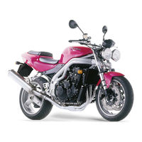
Triumph Speed Triple 2002 Service Manual (385 pages)
Brand:
Triumph
| Category:
Motorcycle
| Size: 21 MB
Table of Contents
Contents
2
General Information
3
Service Tools and Garage Equipment
5
Special Service Tools
5
Full Specification
8
Torque Wrench Settings
15
Maintenance
20
Cylinder Head
22
Cylinder Head and Valves Exploded View
23
Cam Cover Exploded View
24
Camshaft and Camshaft Drive Exploded View
25
Cylinder Head Description
26
Cam Cover Removal
26
Cam Cover Installation
27
Cam Cover Bolt Release Sequence
27
Cam Chain Tensioner Removal
29
Camshaft to Cylinder Head Alignment Marks
29
Cam Chain Tensioner Installation
30
Tensioner Plunger Set-Up
30
Cam Chain Removal
31
Cam Chain Inspection
32
Cam Chain Installation
33
Camshafts Removal
33
Cam Ladder Bolt Release Sequence
34
Camshaft and Bearing Cap Inspection
34
Outrigger Journal Diameter
35
Standard Journal Diameters
35
Measuring the Compressed Plastigage
35
Camshaft Journal Clearance Outrigger
35
Camshafts Installation
36
Cam-Cap and Ladder Bolt Tightening Sequence
36
Valve Clearances
38
Valve Clearance Measurement
38
Typical Valve Clearance Chart
38
Valve Clearance Adjustment
39
Clearance too Small
39
Clearance too Large
39
Cylinder Head Removal
40
Clutch
48
Exploded View - Clutch Cover
49
Exploded View - Clutch Assembly
50
Exploded View - Clutch Controls
51
Clutch Cable Removal
52
Clutch Disassembly
53
Friction Plate Inspection
55
Bend/Warp
56
Assembly
56
Belleville Washer "Out" Mark
57
Balancer
59
Exploded View - Balancer Shaft
60
Balancer Removal
61
Balancer Inspection
62
Balancer Assembly/Installation
62
Crankshaft, Rods and Pistons
65
Crankshaft, Connecting Rod, Piston and Liner Exploded View
66
Exploded View - Crankcase
67
Engine Removal/Refit
68
Engine Installation
71
Crankcases Disassembly
75
Upper Crankcase Bolt Release Sequence
75
Lower Crankcase Bolt Release Sequence
75
Crankcases Assembly
76
Selector Forks
76
Crankshaft Removal
78
Crankshaft Installation
78
Connecting Rods Removal
80
Connecting Rods Installation
81
Connecting Rod Big End Bearing Selection/Crankpin Wear Check
83
Checking the Measured Clearance
83
Connecting Rod Bearing Selection
84
Crankshaft Main Bearing/Journal Wear
85
Pistons Disassembly
86
Removing the Gudgeon Pin Circlip
86
Piston Wear Check
86
Piston Rings/Ring Grooves
86
Piston Ring to Ring Groove Clearance Check
87
Aligning Piston Rings Using the Piston
87
Piston Assembly
87
Piston Ring Identification
87
Cylinder Wear
88
Test Positions for Bore Wear Check
88
Cylinder Liners Removal
89
Cylinder Liners Paint Mark
89
Cylinder Liners Installation
90
Transmission
91
Exploded View, Input and Output Shafts
92
Exploded View, Sprag Clutch and Starter Gears
93
Exploded View, Gear Selectors and Drum
94
Exploded View, Gear Change Mechanism
95
Selector Shaft, Selector Forks & Drum Removal
96
Selector Drum Removal
97
Selector Drum Inspection
98
Selector Fork to Groove Clearance
98
Selector Drum Installation
98
Locating the Selector Drum
98
Input and Output Shafts Assemblies Removal
101
Input and Output Shafts Assemblies Installation
101
Input Shaft Disassembly
102
Input Shaft Assembly
103
Pressing on the Input Shaft Bearing
103
Output Shaft Disassembly
104
Output Shaft Assembly
105
Starter Drive Gears/Sprag Clutch Removal
106
Starter Drive Gears/Sprag Clutch Inspection
107
Starter Drive Gears/Sprag Clutch Installation
108
Lubrication System
109
Exploded View - Sump
110
Exploded View - Oil Pump and Gears
111
Exploded View - Daytona Oil Cooler
112
Exploded View - Speed Triple Oil Cooler
113
Engine Oil Circuitr - Daytona
114
Engine Oil Circuit Description
115
Daytona
115
Engine Oil Circuit - Speed Triple
116
Speed Triple
117
Engine Oil Specification
118
Triumph Engine Oil
118
Oil Level Inspection
119
Oil and Oil Filter Change
119
Disposal of Used Engine Oil
120
Oil Pump Removal
121
Oil Pump Inspection
121
Oil Pump Installation
122
Low Oil Pressure Warning Light Switch
123
Sump Removal
124
Sump Inspection
125
Sump Installation
125
Oil Cooler - Daytona Removal
126
Oil Cooler - Daytona Inspection
126
Oil Cooler - Daytona Installation
126
Oil Cooler - Speed Triple Removal
127
Oil Cooler - Speed Triple Inspection
127
Oil Cooler - Speed Triple Installation
127
Fuel System/Engine Management
128
Exploded View - Fuel Tank and Pump
130
Exploded View - Fuel Rail, Throttle and Injectors
131
Exploded View - Secondary Air Injection Valves and Controls
132
Exploded View - Exhaust System
133
Fuel Requirements
134
Oxygenated Gasoline
134
Methanol
134
Ethanol
134
Calculated Load
135
Catalyst
135
Coolant Temperature Sensor
135
Idle Fuel Trim
135
Long Term Fuel Trim
136
Neutral Switch Status
136
Off Idle Fuel Trim
136
Short Term Fuel Trim
136
Engine Management System Description
137
Engine Management System Sensors
137
Engine Management System Sensor Locations
138
Engine Management System Actuators
139
Engine Management System Actuator Locations
140
Key to Wiring Circuit Diagram
141
Key to Wiring Colour Codes
141
Circuit Diagram - Engine Management System
142
System Diagnosis
143
On-Board Fault Detection System
143
Triumph Diagnostic Tool
143
Current Data
144
Freeze-Frame Data
144
Function Tests
144
Adjustments
144
Diagnostic Trouble Codes
145
Sensor Data
148
Service Diagnostic Tool
148
Typical Screen Showing Symbols Examples
149
Tool Keys
149
Return Key
149
Validation Key
149
Connection and Power-Up
155
Select Language
155
Triumph Motorcycles
156
Switch on Bike Ignition
156
Data Link Fault Retry?
157
Service Data - Dealer
157
Service Data - Date
158
Main Menu
158
Diagnostics
159
Stop Engine
160
Stored DTCS
161
Three Options Are Now Available
161
Freeze Frame
162
Stored DTCS, Erase All DTC Data
163
To Select 'Function Tests' from the Main Menu
163
To Select 'Checks/Adjustments' from the Main Menu
168
Checks
169
Build Data
169
To Access the "Adjustments" Menu
170
Adjust Tune
171
Adjust Tune (Closed Throttle Position)
172
Adjust Tune (Set Adaptive Stepper Position)
172
Adjust Tune (Set Long Term Fuel Trim)
173
Update Tune
173
Update Tune (Confirm Selected)
176
Restarting Tune Download
176
Electrical Components
177
Before Disconnection
177
When Disconnecting a Connector
177
When Inspecting a Connector
177
Engine Control Module
178
Removal of ECM Connectors
178
Refitting of ECM Connectors
178
ECM Connector Pin Numbering
179
Further Diagnosis
179
Fault Finding - Non Electrical
203
Fuel System Adaption
204
Fuel Tank Removal
205
Fuel Tank Installation
206
Fuel Pump Removal
207
Fuel Pump Assembly
207
Fuel Filter Removal
208
Fuel Filter Assembly
208
Fuel Pressure Regulator
209
Fuel Pressure Checking
209
Fuel Delivery System
210
Airbox Removal
211
Airbox Inspection
211
Airbox Installation
212
Air Filter Element Removal
212
Air Filter Element Installation
213
Intake Air Temperature Sensor Removal
213
Intake Air Temperature Sensor Assembly
213
Crankshaft Position Sensor Removal
214
Crankshaft Position Sensor Installation
214
Throttle Cable Adjustment
215
Throttle Cable Removal
216
Throttle Cable Installation
217
Throttle Bodies/Injectors Removal
218
Throttle Bodies/Injectors Inspection
219
Throttle Bodies/Injectors Installation
219
Throttle Body Balancing
221
Throttle Position Sensor Removal
222
Throttle Position Sensor Installation
222
Exhaust System Removal
223
Exhaust System Assembly
225
Secondary Air Injection
226
System Purpose and Operation
226
Secondary Air Injection Solenoid Valve Removal
227
Secondary Air Injection Solenoid Valve Installation
227
Secondary Air Injection Reed Valves Removal
228
Secondary Air Injection Reed Valves Inspection
229
Secondary Air Injection Reed Valves Installation
229
Evaporative Emissions Control System
230
Evaporative Control System - Engine off
231
Evaporative Control System - Engine Running
232
Cooling System
233
Exploded View - Cooling System
234
Coolant
235
Radiator Hoses
235
Radiator and Cooling Fan
235
Coolant Level Inspection
236
Coolant Replacement
236
Drainage
236
Water Pump Removal
238
Water Pump Inspection
238
Water Pump Installation
238
Coolant Pressure Cap Inspection
239
Thermostat Removal
240
Thermostat Inspection
240
Thermostat Installation
240
Radiator Removal
242
Radiator Inspection
243
Radiator Installation
243
Rear Suspension - Twin Sided Swinging Arm Versions
244
Exploded View - Swinging Arm
245
Exploded View - Rear Wheel and Final Drive
246
Exploded View - Drag and Drop Links
247
Exploded View - Rear Suspension Unit
248
Drive Chain Lubrication
249
Chain Adjustment
250
Chain Wear Inspection
251
Rear Suspension Unit Removal
252
Rear Suspension Unit Inspection
253
Rear Suspension Unit Installation
253
Drag Link Removal
254
Drag Link Installation
255
Drop Links Removal
255
Drop Links Inspection
256
Drop Links Installation
256
Swinging Arm/Drive Chain Removal
257
Swinging Arm/Drive Chain Inspection
258
Swinging Arm/Drive Chain Installation
259
Final Drive Removal
260
Final Drive Inspection
260
Final Drive Installation
260
Rear Suspension - Single Sided Switching Arm Versions
261
Exploded View - Single Sided Swinging Arm
262
Exploded View - Single Sided Swinging Arm Rear Hub
263
Exploded View - Rear Suspension Units
264
Exploded View - Single Sided Swinging Arm Drop/Drag Link
265
Final Drive/Rear Hub and Bearings Removal
280
Final Drive/Rear Hub and Bearings Inspection
282
Final Drive/Rear Hub and Bearings Assembly
282
Final Drive/Rear Hub and Bearings Installation
282
Staking the Nut
283
Front Suspension
284
Exploded View - Front Fork
285
Exploded View - Low Handlebars
286
Exploded View - Tall Handlebars
287
Fork Inspection
288
Fork Oil Change
288
Fork Oil Level Chart
290
Fork Pull through
290
Fork Oil Level
290
Front Fork Removal
291
Front Fork Installation
291
Fork Dismantling/Assembly
292
Preload Adjuster Marks
292
Fork Assembly
294
Headstock Bearing Check/Adjustment
295
Checking Headstock Bearing Adjustment
295
Braking System
297
Exploded View - Front Brake Master Cylinder
299
Exploded View - Front Brake Caliper
300
Exploded View - Rear Brake Master Cylinders
301
Exploded View - Rear Brake Caliper
302
Braking System Maintenance Safety Precautions
304
Fluid Level Inspection
305
Changing Brake Fluid
305
Brake Pads
305
Brake Wear Inspection
305
Bleeding the Front Brakes, Renewing Brake Fluid
306
Front Brake Pads Removal
307
Front Brake Pads Installation
308
Front Brake Caliper Removal
308
Front Brake Caliper Disassembly
309
Front Brake Caliper Inspection
309
Front Brake Caliper Assembly
309
Front Brake Caliper Installation
309
Front Discs Wear
310
Front Discs Removal
310
Front Discs Installation
311
Front Brake Master Cylinder Removal
311
Bleeding the Rear Brakes, Renewing Brake Fluid
313
Rear Brake Pads Removal
315
Single Sided Swinging Arm Versions
315
Rear Brake Pads Installation
315
Rear Brake Caliper Removal
316
Rear Brake Caliper Disassembly
316
Rear Brake Caliper Inspection
317
Rear Brake Caliper Assembly
317
Rear Brake Caliper Installation
317
Tyres
326
Exploded View - Front Wheel
327
Tyres Wheel Marking
330
Tyre Marking
330
Tyre Pressures
330
Tyre Wear/Wheel Inspection
331
Minimum Recommended Tread Depth
331
Important Tyre Information
332
Front Wheel Removal
333
Front Wheel Installation
334
Rear Wheel Removal
335
Rear Wheel Installation
335
Bodywork & Frame
338
Exploded View - Frame
339
Exploded View - Seat Rails
340
Exploded View - Cockpit and Mountings
341
Exploded View - Rear Panels
342
Exploded View - Footrests and Mountings
344
Frame, Footrests and Fixings Inspection
345
Seat Removal
345
Seat Refit
346
Side Panel Removal
346
Side Panel Installation
346
Lower Fairings Removal
347
Lower Fairings Installation
347
Cockpit Removal
348
Cockpit Installation
348
Electrical System
349
Exploded View - Instruments
350
Exploded View - Daytona Headlight
351
Exploded View - Speed Triple Headlight
353
Exploded View - Rear Light and Indicators
354
Exploded View - Alternator and Starter
355
Battery Removal
356
Battery Refit
356
Battery Commissioning and Charging
357
New Battery
357
Table of Charging Times
357
Battery Already in Service
357
Fuses
358
Relay Identification
358
Fuse Identification
358
Instrument Pack Removal
359
Instrument Pack Installation
359
Headlights - Daytona 955I
360
Headlight Bulb Replacement
361
Position Lamp Bulb Replacement
361
Headlights - Speed Triple
362
Rear Light
364
Indicator Light
364
Licence Plate Light
364
Starter Motor Removal
365
Starter Motor Inspection
365
Starter Motor Installation
365
Alternator Removal
366
Alternator Assembly
367
Alternator Rectifier
367
Lighting Circuit Diagram - Daytona
368
Starting and Charging Circuit Diagram
373
Auxiliary Circuit Diagram
375
Alphabetical Index
377
Advertisement
Advertisement
Related Products
Triumph Speed Triple
Triumph Speed Triple R
Triumph speed triple 1050
Triumph Speed Triple S
Triumph Speed Triple RS
Triumph Speed Triple 1200 RR 2022
Triumph Speed Triple 1200 RS 2022
Triumph Speed Twin 2019
Triumph Speed Twin
Triumph Speed 400 2023
Triumph Categories
Motorcycle
Automobile
Motorcycle Accessories
Sports & Outdoors
Lifting Systems
More Triumph Manuals
Login
Sign In
OR
Sign in with Facebook
Sign in with Google
Upload manual
Upload from disk
Upload from URL