Sign In
Upload
Manuals
Brands
Treetech Manuals
Monitor
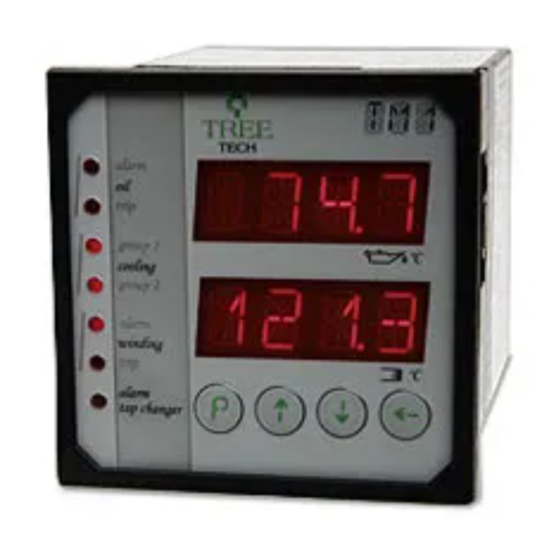
TM1
User Manuals: Treetech TM1 Temperature Monitor
Manuals and User Guides for Treetech TM1 Temperature Monitor. We have
1
Treetech TM1 Temperature Monitor manual available for free PDF download: Technical Manual
Treetech TM1 Technical Manual (95 pages)
Temperature
Brand:
Treetech
| Category:
Monitor
| Size: 3 MB
Table of Contents
Table of Contents
2
List of Figures
4
1 Foreword
6
Legal Information
6
Presentation
6
Typographical Conventions
6
General and Safety Information
6
Safety Symbols
7
General Symbols
7
Minimum Profile Recommended for the TM1/TM2 Operator and Maintainer
7
Environmental and Voltage Conditions Required for Installation and Operation
8
Instructions for Test and Installation
8
Table 1 - Operating Conditions
8
Cleaning and Decontamination Instructions
9
Inspection and Maintenance Instructions
9
Technical Assistance
10
Warranty Term
11
Revision Control
12
Table 2 - Revision Control
12
2 Introduction
13
Main Features
13
Figure 1 - Temperature Monitors Tm1 and Tm2
14
Optional Features
15
Operation Philosophy
16
Figure 2 - Temperature Measurements of Ltc, Transformer and Temperature Differential
17
Figure 3 - Instantaneous and Filtered Temperature Differentials
18
3 Operation
19
Initial Settings
19
Figure 4 - Temperature Indications
19
Figure 5 - Signaling Leds on Temperature Monitor Tm1
20
Figure 6 - Signaling Leds on Temperature Monitor Tm2
20
Function of Keys
21
Consultation Screens
21
TM1 Consultation Screens
21
Figure 7 - Self Diagnostic Indications
21
Consultation Screen TM2
23
Commands
24
4 Project and Installation
26
System Topology
26
Inputs and Outputs
26
Figure 8 - Block Diagram
26
Project and Installation
28
Table 4 - Tm1/Tm2 Outputs
28
RTD Temperature Sensors
29
Figure 9 - Detail Shield Connection of Rtd Sensor
30
Serial Communication Ports RS485
30
Analogic Outputs
31
Current Transformers
31
Figure 10 - Shield Connection of Serial Communication
31
Figure 11 - Connection Details of Current Transformers Directly Temperature Monitors
32
Figure 12 - Connection Details of Current Transformers to Temperature Monitors Prepared for External Cilip-On Cts
33
Forced Cooling Control
33
Figure 13 - Command of 4 Equal Forced Cooling Groups Shifting the Operation of Groups
35
Figure 14 - Command of 1 Forced Cooling Group with Pumps and 3 Equal Groups with Fans Shifting the Operation of Fan Grops
36
Figure 15 - Comman of 2 Equal Forced Cooling Groups with Pumps and 2 Equal Groups with Fans, with Independente Shifting for the Operation of the Pump Groups and the Fan Groups
37
Figure 16 - Command of 4 Equal Forced Cooling Groups in 2 Temperature Stages, with Timer for Motors Start and Shifting the Groups
39
Figure 17 - Command of 2 Equal Forced Cooling Groups with Command Redundancy
40
Typical Application Diagrams
41
Figure 18 - Option 1 - 2 Rtds with 3 Wires
41
Figure 19 - Option 2 - 1 Rtd with 4 Wires
42
Figure 20 - Option 3 - 1 RTD with 3 Wires, RTD a
43
Figure 21 - Option 4 - 1 RTD with 3 Wires, RTD B
43
Figure 22 - Connection Tm1/Tm2
44
Figure 23 - Connection Tm1 / Mt2
44
Figure 24 - Connection Mt1 / Tm2
45
Figure 25 - Connection Tm1 / Synchronism Signal Irig-B
45
Mechanical Installation
46
Figure 26 - Dimensions of Tm1 and Tm2
46
5 Parameterization
47
Programming
47
Access to the Programming Menu
48
Access to Submenus
49
Submenu LNG
50
Submenu CLK
50
Submenu ALM
51
Submenu CNF
53
Submenu TRF
61
Technical Manual - TM1/TM2 | MA-010| 2016-03-21 | Ver
62
Submenu FAN
65
Submenu LTC
69
Submenu LOG
71
Typical Adjusts
73
6 Start-Up Procedure for Puttin Equipment in Operation
74
7 Troubleshooting
80
The Device Displays Self-Diagnosis Messages on the Display
80
Figure 27 - Self Diagnostic Indications
80
Table 6 - Digit 1 Failures
81
Table 7 - Digit 2 Failures
82
Table 8 - Digit 3 Failures
84
Table 9 - Digit 4 Failures
86
Tm1/Tm2 Reads Incorrect Values for Temperatures
87
Table 10 - Incorrect Reading of Values for Temperatures
87
Tm1/Tm2 Reads Incorrectly Values for Load Currents
88
Tm1/Tm2 Indicates Incorrect Values for Winding Temperatures
88
Tm1 Does Not Communicate with the Data Acquisition System
88
Table 11 - Incorrectly Values for Load Currents
88
Table 12 - Incorrect Values for Winding Temperatures
88
Table 13 - N O Communication between Tm1 and Data Acquisition System
88
Remote Reading through Analog Output Incorrect
89
Tm1/Tm2 Does Not Correctly Activate the Forced Cooling
89
Table 14 - Remote Reading through Analog Output Incorrect
89
Table 15 - Incorrect Activate the Forced Cooling
89
8 Attachments
90
Attachmenta
90
Attachmentb
91
Attachmentc
92
Attachmentd
93
Table 16 - Compatibility between Firmwares
93
Advertisement
Advertisement
Related Products
Treetech TM2
Treetech IDM
Treetech Categories
Monitor
Measuring Instruments
Controller
More Treetech Manuals
Login
Sign In
OR
Sign in with Facebook
Sign in with Google
Upload manual
Upload from disk
Upload from URL