Sign In
Upload
Manuals
Brands
Toshiba Manuals
Inverter
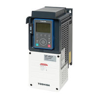
VFAS3-4550PC
Toshiba VFAS3-4550PC Manuals
Manuals and User Guides for Toshiba VFAS3-4550PC. We have
1
Toshiba VFAS3-4550PC manual available for free PDF download: Instruction Manual
Toshiba VFAS3-4550PC Instruction Manual (644 pages)
Industrial inverter
Brand:
Toshiba
| Category:
Inverter
| Size: 29 MB
Table of Contents
Explanation of Markings
3
Meanings of Symbols
3
Safety Precautions
3
Introduction
13
Table of Contents
15
Read First
21
Check Product Purchase
21
Rating Label
22
Quick Start
23
Multi-Rating
24
Indication of Product Type
25
Type-Form
25
Frame Size
26
Structure of Equipment
27
Outside View
27
Operation Panel and Peripherals
29
Terminal Blocks
31
Control Terminal Block
32
Features of Inverter
33
Operation Procedure
34
Installation and Wiring
37
Installation
38
Installation Environment
38
How to Install
40
Basic Installation
41
Side-By-Side Installation
41
How to Remove Covers of Inverter
47
With Frame Size A1, A2, or A3
48
VFAS3-2004P to 2075P, VFAS3-4004PC to 4185PC
48
Front Cover
48
Top Cover
49
With Frame Size A4
50
With Frame Size A5
51
VFAS3-2220P to 2370P, VFAS3-4450PC to 4750PC
51
Wiring Cover
52
With Frame Size A6
53
Vfas3-2450P, 2550P
53
VFAS3-4900PC to 4132KPC
53
With Frame Size A7 and A8
55
VFAS3-4160KPC to 4280KPC
55
Charge Lamp
59
Wiring
62
Cautions for Wiring
62
Installation and Wiring
63
Standard Connection Method
65
Braking Resistor
66
DC Power Supply
66
Digital Input
72
Power Terminals
79
Switching of Grounding Capacitor
84
Control Terminals
92
RS485 Communication Ports
99
Ethernet Ports
99
Mounting of DC Reactor
100
Cautions for Application
103
Motor
103
Inverters
105
What to Do about Leakage Current
107
Basic Operation] Operation Panel and Screen Display
111
Basic of Operation Panel
111
LCD Screen and Operation Keys
111
Display Mode
116
Function Area
118
Setting of LCD Screen
122
Contrast Adjustment
123
Automatic off Time
123
Copy Function
124
Normal/Emergency Screen Display
128
Normal Display
128
Display at the Time of Trip
129
Emergency off
130
How to Reset Trip
131
Basic Operation]
133
Operation Methods of Motor
133
To Run/Stop Motor
134
Basic Setting Methods of Parameters
135
Setting Mode] and [Easy Mode]
135
History Function
136
Direct Access
138
Basic Parameters and Extended Parameters
147
Basic Operation of Parameter Setting
147
Basic Panel Run Methods
152
Operation Example 1] Operating with [RUN] Key/[Stop] Key on Operation Panel
152
Operation Example 2] Switching Forward/Reverse Run with [FWD/REV] Key During Panel Run
155
Basic Terminal Run Methods
159
Operation Example 1] Run/Stop with External Signal (Frequency Command with Operation Panel)
159
Press the [OK] Key
162
Operation Example 2] Setting Frequency with External Potentiometer/Analog Signal
163
Operation Example 3] Switching Run/Stop and Frequency with External Switch
170
Fundamental Operation] How to Use Parameters
175
Table of Parameter Access
175
Settings of Main Parameters
175
Selecting How to Input Run and Frequency Commands
175
Parameter Setting
177
Setting Rated Frequency and Rated Voltage of Motor
181
Setting the Output Frequency Limit
183
Setting Acceleration/Deceleration Time
186
Protecting the Motor from Overload
188
Adjusting the Meter Connected to the Inverter
193
Selecting the Display Units for Current and Voltage
198
Selecting the Parameter Mode between [Setting Mode] and [Easy Mode]
200
Returning Parameters to Their Default Settings Clearing each History
202
Registering Parameters Suitable for the Application in [Easy Mode]
208
Setting Other Basic Parameters
210
Setting Energy Savings
210
Selecting an Overload Protection Characteristic
211
Acceleration/Deceleration Time Adjustment Automatically According to Load
212
Selecting Motor Control Method
214
Automatic Torque Boost
215
Manual Setting
217
Setting Parameters for Torque Boost and Energy Saving Easily
223
Increasing Starting Torque
225
Operating by Switching Frequency Command with External Logic Signal
226
Parameter Setting
226
Setting PID Control
230
Switching Direction of Rotation During Panel Run
235
Automatic Setting of Main Parameters by Region Used
237
Setting of Extended Parameters that Are Especially Important
240
Switching Two Frequency Commands
240
Restarting Smoothly after Momentary Power Failure
243
Customizing Display
246
Advanced] How to Use Parameters
253
Output Signals from the Control Terminals
253
Output the Running Signal and the Brake Signal (Low-Speed Signal)
253
Output a Signal When Reached to a Frequency Command (Acc/Dec Completed Signal)
255
Output a Signal When Reached to a Specified Frequency (Specified Frequency Attainment Signal)
257
Input Signals to the Control Terminals
259
Selecting Operation at Simultaneous Input of Fwd/Rev Commands
259
Selecting Input Voltage of the Terminal [RX]
261
Selecting Input Signal of the Terminal [RR]
262
Parameter Setting
262
Selecting Input Signals of the Optional Terminals [AI4] and [AI5]
263
Selecting Terminal Functions
264
Always Enabling the Input Terminal Functions (Always ON)
264
Changing the Input Terminal Functions
266
Changing the Output Terminal Functions
267
Switching Two to Four Types of Motor Characteristics
268
V/F 5-Point Setting
271
Setting the Frequency Commands
272
Switching Two Types of Frequency Commands
272
Setting Frequency Command Characteristics by Analog Signals
272
Setting Method
275
Fine Adjusting the Analog Frequency Commands
276
Parameter Setting
277
Adjustment Method
277
Input the Frequency Commands by Pulse Trains
279
Changing Frequency by the Terminal up and down Signal
281
Setting the Start and End Frequencies
284
Setting the Starting Frequency and the End Frequency
284
Run/Stop with a Frequency Command
285
Setting a Frequency Command to 0 Hz Securely
286
Coast Stop at any Frequency
287
DC Braking
288
Obtaining Large Torque with DC Braking
288
Fixing the Motor Shaft with DC Braking
290
Making the Motor Standstill with PG Feedback Control
292
Automatic Stop When Run Continues at the Lower Limit Frequency (Sleep Function)
294
Jog Run
296
Jumping the Frequency to Avoid the Resonant Frequency
298
Setting the Preset-Speed Operation Frequency
300
Forced Run in Emergency
300
Bumpless Operation
302
Changing Carrier Frequency to Reduce Noise and Magnetic Noise
304
Avoiding Trips
306
Restarting Smoothly after Momentary Power Failure (Restarting from Motor Coasting State)
306
Selecting Operation for Momentary Power Failure
306
Automatic Reset at Trip (Retry Function)
311
Dynamic Braking - Abrupt Motor Stop
313
Avoiding Overvoltage Trip
316
Adjusting and Limiting Output Voltage
318
Inhibiting Reverse Run
320
Single Load Sharing by Multiple Inverters (Droop Control)
321
High-Speed Operation with Light Load on Cranes
324
Brake Sequence
325
Hit and Stop Control
325
Minimum Inching Interval
325
Constant Speed Run with Acc/Dec Suspended (Dwell Operation)
327
Switching to Commercial Power Run
330
Parameter Setting
330
PID Control
333
Retaining the Stop Position
333
PG Feedback
334
PG Feedback Built-In Function
334
Digital Encoder Option
334
Resolver Option
334
Setting of Motor Parameters
335
Setting Induction Motor Parameters
335
Setting PM Motor Parameters
343
Torque Limits
352
Switching Torque Limits
352
Selecting Acc/Dec Operation after Stall Prevention Operation
356
Minimum Time
357
Detecting the Stall Time During Power Running to Trip
358
Selecting Stall Operation During Regeneration
360
Torque Control
361
Setting External Torque Commands
361
Speed Limit During Torque Control
361
Selecting Tension Control Torque Bias Input and Load Sharing Gain Input
362
Adjusting Current and Speed Control Gain
364
Setting Current and Speed Control Gain
364
Setting the over Modulation Ratio
364
Switching Multiple Acceleration/Deceleration
365
Setting Acc/Dec Patterns
365
Switching Four Types of Acceleration/Deceleration
367
Pattern Operation
371
Shock Monitoring Function
375
Setting the Protection Functions
376
Setting the Motor Electronic Thermal Protection
376
Setting Overcurrent Stall
377
Parameter Setting
377
Retaining Trip Types
378
Emergency off
380
Output Phase Loss Detection
382
Input Phase Loss Detection
384
Undercurrent Detection
385
Overtorque Detection
387
Short Circuit Detection at Start
389
Ground Fault Detection
390
Cooling Fan Control
391
Cumulative Run Time Alarm Setting
393
Speed Error (over Speed) Detection
393
Undervoltage Trip Setting
396
Brake Answer Waiting Time Setting
398
Analog Input Disconnection Detection
399
Setting Parts Replacement Alarm by the Ambient Temperature
401
Rush Current Suspension Relay Control
403
Parameter Setting
403
Motor PTC Thermal Protection Setting
404
Protecting the Control Power Supply Option Unit at a Time of Failure
406
Setting Number of Starting Alarm and Alarm Occurrence of the Specified Trip
408
Setting Cumulative Overcurrent Level and Time
410
Adjusting the Overheat Alarm Level
411
Generatin Trip for Test
412
Detects Belt Breakage (Low Torque)
413
Forced Run Control in Emergency
415
Frequency Adjustment Using External Input (Override Function)
417
Adjustment Parameters
420
Pulse Output Based on Input Cumulative Power by a Fixed Integral Value
420
Pulse Train Output
421
Analog Output Adjustment
423
Setting Functions of Operation Panel
426
Lockout Key Operation and Parameter Setting
426
Changing Current/Voltage Display from Percentage to Unit (A/V)
429
Displaying Motor or Line Speed
429
Changing Variation Steps of Panel Display
430
Parameter Setting
430
Selecting Data Displayed in [Standard Mode]
432
Changing Display in [Monitor Model]
432
Holding Display in [Standard Mode]
433
Clearing Run Command
434
Selecting Panel Stop Pattern
436
Setting Torque Command Value in Panel Run
437
Selecting Panel Display at Power on
438
Changing the Reference Website of QR Code
440
Trace Function
441
Store Cumulative Power
442
Select EASY Key Function
443
Communication Functions
445
Setting Communication Functions
445
Communication Protocol
446
Using RS485 Communication
450
Modbus Rtu Protocol
450
Input Numbers as Memorandum
451
Step-Out Detection of PM Motor
452
Traverse Function
453
My Function
454
Application and Option Manual List
455
Operating Using External Signals
457
How to Externally Operate the Inverter
457
Applied Operation by I/O Signals
458
Setting the Functions to the Input Terminals
458
Setting the Functions to the Output Terminals
464
Frequency Commands by the Analog Signals
470
Inputting Frequency Commands by Analog Signals
470
Inputting the Frequency Commands by Potentiometer/Voltage (0 - 10 VDC)
473
Inputting the Frequency Commands by Current (4 - 20 Madc)
474
Inputting Frequency Commands by Voltage (-10 to +10 VDC)
475
Monitoring the Inverter Status in Operation / before Tripping
477
Screen Display of [Monitor Mode]
477
Operation Status Monitor
477
Direction of Rotation
479
Input/Output Terminals
480
Communication Status
481
Detailed Display of Past Trip
486
Information Display
487
Screen Display at Trip Occurrence
488
Display of Trip Information and Alarm Information
488
Monitor Display at Trip
488
Measures to Satisfy Standards
489
How to Deal with CE Marking
489
Compliance with EMC Directive
489
Compliance with Low Voltage Directive
492
Compliance with Safety Standards
493
Compliance with ATEX Directive
493
Compliance with UL/CSA Standards
494
Compliance with Installation
494
Compliance with Connection
494
Cautions for Peripheral Devices
495
Overload Protection
501
Motor Thermal Protection
501
Motor Integrated PTC Thermal Protection
501
Selection and Installation of Peripheral Devices
503
Selection of Wire Size
503
Selection of a Wiring Device
506
Selection Table of a Wiring Device
506
Installation of a Molded-Case Circuit Breaker (MCCB) and Earth Leakage Circuit Breaker (ELCB)
509
Installation of a Magnetic Contactor (MC)
509
Installation of a Thermal Relay (THR)
511
External Options
512
Input AC Reactor, (DC Reactor)
512
Braking Resistor, Braking Unit
513
Output Filter
513
Optional Control Power Supply
513
LED Extension Panel Option
514
USB Communication Conversion Unit
514
Flange Mounting Kit
514
Door Mounting Kit
514
External Option List
515
Insert Type Options
516
Insert Type Options and Functions
516
Mounting/Removing Insert Type Options
517
Mounting/Removing the Option Adaptor
518
Table of Parameters
523
Frequency Setting Parameter
523
Basic Parameter
524
Extended Parameter
528
Advanced Parameter
566
Communication Parameter
567
Parameter Setting Range and Default Setting Depending on Capacity
568
Analog Output/Monitor Output Function
574
Input Terminal Function
578
Output Terminal Function
582
Setup Menu
587
Guidance Function
588
Specifications
589
Model and Main Standard Specification
589
Outside and Mass
597
Outline Drawing
598
Trip Information and Measures
607
Description of Trip and Alarm Information and Measures
607
How to Reset Trip
621
If Motor Does Not Run While No Trip Message Is Displayed
623
How to Determine Causes of Other Problems
624
Maintenance and Inspection
627
Daily Inspection and Cleaning
627
Checkpoints for Daily Inspection
627
Daily Cleaning
628
Periodical Inspection
629
Checkpoints for Periodical Inspection
629
Periodical Inspection on the Replacement Parts
630
How to Replace the Battery
632
In Case of a Failure
633
Cautions for Storage
633
Measuring Method of each Part
634
Power Circuit
634
Control Circuit
635
Checking Method of Power Circuit under Unusual Conditions
636
Warranty
639
Disposal
641
Advertisement
Advertisement
Related Products
Toshiba VFAS3-4370PC
Toshiba VFAS3-4150PC
Toshiba VFAS3-4015PC
Toshiba VFAS3-4075PC
Toshiba VFAS3-4450PC
Toshiba VFAS3-4055PC
Toshiba VFAS3-4300PC
Toshiba VFAS3-4185PC
Toshiba VFAS3-4007PC
Toshiba TOSVERT VFAS1-4900PC
Toshiba Categories
Laptop
Air Conditioner
TV
LCD TV
All in One Printer
More Toshiba Manuals
Login
Sign In
OR
Sign in with Facebook
Sign in with Google
Upload manual
Upload from disk
Upload from URL