Sign In
Upload
Manuals
Brands
TOMARK Manuals
Aircrafts
Viper SD-4 RTC
TOMARK Viper SD-4 RTC Manuals
Manuals and User Guides for TOMARK Viper SD-4 RTC. We have
1
TOMARK Viper SD-4 RTC manual available for free PDF download: Maintenance Manual
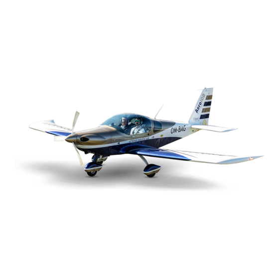
TOMARK Viper SD-4 RTC Maintenance Manual (203 pages)
Airplane
Brand:
TOMARK
| Category:
Aircrafts
| Size: 4 MB
Table of Contents
Preceding
1
Table of Contents
6
List of Figures
14
Introduction
16
General
16
Coverage
16
Guidelines
16
Related Publications
17
Addresses
18
How to Use the Manual
19
General
19
Notes
20
Terminology and Abbreviations
21
Standard Elements
21
Safety
22
General Description
23
General
23
Limitations
24
General
24
Structural Limitations and Inspection Intervals
24
Placards
25
Major Inspection
25
Major Inspection Airframe
25
Major Inspection Engine Mount
26
Inspection and Maintenance
28
General
28
Time Limits and Inspection Program
28
Component Time Limits
29
Scheduled Maintenance
30
Scheduled Inspection Plan
30
Lubrication Chart
49
Drain Holes
56
Maintenance Check Flight
57
Performance Tests
58
System Tests
59
Flight Controls
59
Engine Controls
60
Other Controls
60
Flight Instruments
61
Avionics
61
System
62
Engine Monitoring System (EMS)
63
Other Instruments
64
Flight Handling Tests
65
Unscheduled Maintenance
66
Inspection after Spin-Event
66
Aircraft Geometry Check
67
Measuring Sections
68
Measuring Points Identification
69
Dimensions and Areas
70
General
70
Coordinate System
70
External Dimensions
70
Wing
70
Aileron
70
TOMARK, S.r.o
71
Flap
71
Horizontal Tail
71
Elevator
71
Elevator Trim Tab
71
Vertical Tail
71
Aileron Trim Tab
71
Rudder
72
Fuel System
72
Landing Gear
72
Propeller
72
Lifting and Shoring
73
Lifting a Main Wheel
73
Lifting the Nose Wheel
74
Jacking
75
Jacking the Aircraft Side
75
Jacking the Aircraft Front
76
Leveling & Weighing
77
Weighing and Balancing
77
Leveling
81
Servicing
82
Replenishing
82
Refueling/Defueling
82
Oil Change
82
Coolant Replacement
83
Brake Fluid Bleeding
83
Brake Fluid Replenishing
84
Standard Practices-Airframe
86
Bolts
86
Rivets
86
Hoses and Tubes
89
Bowden Cables
90
Air Conditioning
91
Distribution
91
Heating
92
Heating System
93
Electrical Power
94
General
94
DC Generation
94
Generator
94
Battery
94
Signaling
95
Distribution
95
Electric Current Protection
95
Equipment and Furnishings
96
Flight Compartment
96
Seats
96
Seat Belts
96
Paneling
96
Baggage Compartment
97
Flight Controls
98
Control System
99
Control Stick
100
Control Rod
100
Bell Crank
100
Bracket
101
Aileron Control
102
Aileron
103
Aileron Trim
104
Rudder Control
104
Rudder
105
Rudder
106
Elevator and Tab
107
Elevator
108
Elevator Trim
109
Flap System
110
Issue: 11.AUG
110
Flap
111
Fuel
113
Fuel System
114
Storage
115
Drain Valve
115
Distribution
115
Indication
115
Indication & Recording Systems
116
Instrument Panel
117
Panel
119
Typical Instruments
119
Typical Switches/Circuit Breakers
120
Landing Gear
121
Main Gear
122
Main Gear Leg
122
Nose Gear
123
Nose Gear Strut Fairing
123
Nose Wheel Fairing
123
Wheel Fork
123
Shock Cord Ring
124
Shock Cord Ring Replacement
125
Steel Cable Deflection Limiter
127
Wheels and Brakes
127
Main Wheel Fairing
127
Main Wheel
128
Brake Cylinder
129
Brake
129
Brake Linings
130
Brake Disc
130
Nose Wheel
131
Steering
131
Lights
132
Position / Strobe Light
132
Landing Light
133
Landinglight Removal / Installation
134
Navigation
135
Standard Practices Structure
136
Access Hatches, Covers and Fairings
136
Access Hatch
138
Control Surface Balancing
139
Rudder Balancing
141
Aileron Balancing
142
Repair
144
Repair of Metal Skins
144
Removing Damaged Skins
146
Removing Small Dents
146
Stopping Cracks
147
Repairing the Skins with Patches
147
Location of Patches on the Airplane Skin
148
Repair of the Punctured Skin in the Frame Area
149
Repair of the Punctured Skin
150
Repair of U-Profile
151
Repair of Composite Parts
151
Parts of External Appearance
152
Small Damage
152
Medium Damage
154
Major Damage
156
Structural Parts
156
Small Damage
156
Repair of Paint
157
Small Damage
161
Fuselage
163
Canopy
164
Fuseage Tail Fairing
164
Stabilizers
165
Stabilizer Tip Fairings
165
Horizontal Stabilizer
166
Elevator
166
Rudder
167
TOMARK, S.r.o
167
Vertical Stabilizer
167
Wing
168
Center Wing
169
Wing Root Fairing
169
Wing Tips
170
Wing Tip Fairing
170
Flaps
170
Ailerons
170
Propeller
171
Propeller Blade
171
Spinner
171
Power Plant
172
Top Engine Cowling
172
Bottom Engine Cowling
172
Air Intakes
173
Engine
174
Inlet Section
174
Carburetor Preheating
174
Engine Fuel and Control
175
Controlling
175
Throttle Lever
175
Choke Control Knob
175
Ignition
176
Air
177
Engine Cooling
177
Coolant Thermostat
177
Indicating
178
Coolant Temperature
178
Oil
179
Storage
179
Oil Tank
179
Distribution
179
Oil Gear Pump
179
Oil Radiator
180
Oil Filter
180
Oil System Ventilation
180
Oil Temperature Sensor
180
Oil Thermostat
180
Starting
181
Starter
181
Emergency Equipment
182
Aircraft Emergency Parachute System (AEPS)
182
Aeps
183
Charts
186
Figure
187
Figure
188
Figure
189
Figure
190
Figure 41 FU3 Power Supply for Fuel Pump
191
Figure 42 FU2 Power Supply for SV-EMS220 Module and EMS Display
192
Figure 43 FU15 Power Supply for Intercom
193
Figure 44 FU7 Power Supply for Radio
194
Figure 45 FU1 & FU9 Power Supply for EFIS Display and Transponder
195
Figure 46 FU5 Power Supply for Flaps
196
Figure 47 FU8 Power Supply for GPS
197
Figure 48 FUL & FU6 Power Supply for Strobo Lights and Nav Lights
198
Figure 49 FU10 Power Supply for Socket 12/1A
199
Figure 50 FU4 Power Supply for Starter Power
200
Figure 51 FU4 Power Supply for Starter Power
201
Figure 52 Mounting Rod and Cup for Nose Gear Tensioning Tools
202
Figure 53 Check Flight Form
203
Advertisement
Advertisement
Related Products
TOMARK Categories
Aircrafts
More TOMARK Manuals
Login
Sign In
OR
Sign in with Facebook
Sign in with Google
Upload manual
Upload from disk
Upload from URL