Sign In
Upload
Manuals
Brands
Toa Manuals
Security System
VX-2000 Series
Toa VX-2000 Series Manuals
Manuals and User Guides for Toa VX-2000 Series. We have
3
Toa VX-2000 Series manuals available for free PDF download: Instruction Manual, System Design Manual, Installation Manual
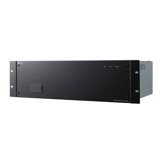
Toa VX-2000 Series Instruction Manual (328 pages)
Integrated Voice Evacuation System
Brand:
Toa
| Category:
Security System
| Size: 6 MB
Table of Contents
Table of Contents
2
Safety Precautions
10
Chapter 1: NOTE
12
General Description
13
System Features
14
Handling Precautions
16
Chapter 2: PRODUCT DESCRIPTIONS
17
Maximum System Example
18
Block Diagram
18
Maximum System Configuration Table
19
Nomenclature and Functions
20
Fireman's Microphone Rm-200Xf
20
Remote Microphone Rm-200X
22
Remote Microphone Extension
24
Voice Announcement Board
27
Remote Microphone Input Module VX-200Xr
28
Audio Input Module with Control Input VX-200XI
29
Surveillance Frame VX-2000Sf
30
Pilot Tone Detection Module VX-200SP
32
Impedance Detection Module VX-200SZ
33
Equaliser Card VX-200SE
34
Control Input Module VX-200SI
35
Control Output Module VX-200SO
36
Power Amplifiers VP-2064, VP-2122, VP-2241, and VP-2421
37
Power Amplifiers VP-3154, VP-3304, and VP-3504
38
Power Amplifier Input Module VP-200VX
40
Chapter 3: SYSTEM OPERATION OUTLINE
41
Operation Modes
42
Drive Mode
42
System Operation Mode
42
Monitor Function
43
Continuous Monitoring
43
Monitoring that Requires Interval Settings
44
Amplifier Standby Functions
45
Speaker Line Failure Detection Methods
46
Impedance Detection Method
46
Pilot Tone Detection Method
46
External Attenuator Control Terminal Operation
47
Operation
47
Operation During Monitoring
48
Cpu Switch
49
Switching off System Power
50
Broadcast Priorities
51
Duplicate Broadcasts from both Higher and Lower Priority Equipment
52
Fifo/Lifo Priorities
53
Broadcasts from the Daisy-Chain Connected Remote Microphones
54
Chapter 4: FUNCTIONS
56
Operation Outline
57
Patterns
58
Emergency Broadcast Patterns
58
Control/General-Purpose Broadcast Patterns
59
Failure Output Patterns
60
Activation Items
61
Remote Microphone Function Keys
61
Emergency
62
Audio Monitoring
63
Base Pattern Change
63
Base Pattern End
63
Control Output Interlock
63
Failure Output Reception
64
Failure Output Reset
64
Volume down Operation
64
Volume up Operation
64
All-Zone Selection
65
Clear
65
Zone Selection
65
Talk
66
Chime
67
General-Purpose EV Message
67
Control Input
68
Internal Timer
69
Preparing Day Programs
69
Timer Management
70
Summer Time Settings
71
Activation Item Function Table
72
Chapter 5: OPERATION
73
Operating the Remote Microphone by Using a Password
74
Entering a Password
74
Bringing the Remote Microphone into Password Entry Status
74
Emergency Broadcasts
75
Dual-Origin EV Message Broadcast
75
Single-Origin EV Message Broadcast (Sequential Operation)
80
Emergency Mode Activation and Reset
84
General-Purpose Broadcast
91
Making Announcements from the Remote Microphone
92
Making Bgm Broadcasts
94
Recalling Base Patterns Using the Internal Timer
94
Recalling Base Patterns from the Remote Microphone
96
Changing the Input Sensitivity and Output Volume Level
98
Changing the Input Sensitivity and Output Volume Level at the Remote Microphone
98
Changing the Input Sensitivity and Output Volume by Way of the Control Input or Internal Timer
101
Interrupt Broadcasts
102
EV Message Broadcasts
103
Making EV Broadcasts from the Remote Microphone
103
Making EV Broadcasts by Way of the Control Input or Internal Timer
104
Audio Monitoring
105
Monitoring by Means of a Remote Microphone
105
Monitoring by Means of the VX-2000'S Monitor out Terminal
105
Failure Output Detection
106
Failure Output Indication
106
Monitoring Log List
109
Chapter 6: FLOWCHART from SYSTEM SETUP to OPERATION
112
Procedure to System Operation
113
Chapter 7: PC SOFTWARE OFFLINE SETTINGS
116
SETUP PROCEDURE (from Installation to Settings)
117
HARDWARE Requirement
119
Software Installation
120
Screen and Menu Descriptions
123
Screen
123
Menu
124
VX-2000 Setting Software Activation
125
New File Creation
126
Configuration Setting Mode
128
Sf Module Properties Setting
128
Control Output Name Setting
134
VX-2000 Properties Settings
135
Remote Microphone Properties Settings
138
Remote Microphone (Rm) Unit Expansion
140
Electronic Voice File (EV) Unit Message Types
143
Monitor Settings
144
System Setting Mode
145
Broadcast Priority Settings
145
Emergency Rm
146
Emergency EV
147
General (General-Purpose Broadcast)
148
Bgm
149
Initial Source Input Volume Settings
150
Initial Volume Settings
150
Initial Output Volume Settings
151
Equaliser Settings
152
Operation Setting Mode
154
Emergency Broadcast Settings
154
When no EV Units Are Used
154
When Using a Single EV Unit
155
When Using 2 EV Units
157
Control Output Interlock Pattern
160
Pattern Creation
160
Interrupt Broadcast Pattern
161
EV Broadcast Pattern
162
Base Pattern
163
Volume Pattern
165
Failure Output Pattern Creation
166
Activation Setting Mode
167
Remote Microphone Function Key Assignment
167
Control Input Settings
171
Timer Settings
173
Day Programs
173
Weekly Program
175
Holiday Programs
176
Summer Time
177
Printing out Setting Data
178
Chapter 8: INSTALLATION and SETTING PROCEDURES (HARDWARE)
179
Rm-200Xf and Rm-200X Microphones
180
DIP Switch Settings
180
DIP Switch Functions
180
Unit ID Number Settings (Switches 1 - 4)
181
Microphone Input Sensitivity Adjustment Using Level Meter Mode (Switch 5)
182
(Switches 7 and 8, and Rm-200Xf Only)
183
Compression Settings (Switch 6)
183
Enable/Disable Switching for the Emergency Button and Function Key
183
Rm-200Xf Wall Mounting
184
Mounting the Assembly of Rm-200Xf and Its Extension Rm-210 on a Wall
186
Rm-200X Wall Mounting
188
Mounting the Assembly of Rm-200X and Its Extension Rm-210 on a Wall
189
Rm-200X Expansion with the Addition of the Rm-210 (Installed on a Flat Surface)
191
Creating Remote Microphone Name Labels
192
VX-2000, VX-200Xr, VX-200Xi, and
193
Removing the VX-2000'S Top and Front Panels
193
Changing the Rs-232C Connector Location
194
Insulating the VX-2000 Control I/O
195
Installing the Insulating Transformer in the VX-2000 System Manager
196
Mounting the EV-200 Voice Announcement Board on the VX-2000 System Manager
197
Setting the VX-200XI Audio Input Module DIP Switch
199
Insulating the VX-200XI Control and Audio Inputs
200
Mounting the VX-200Xr and VX-200XI in the VX-2000 System Manager
201
VX-2000 System Manager's DIP Switch Settings
201
DIP Switch Functions
201
Setting the VX-2000'S Uk Standby Mode (Switch 5)
201
VX-2000Sf, VX-200Sz , VX-200Sp, VX-200Si , VX-200So, and VX-200Se
202
VX-2000Sf Surveillance Frame's DIP Switch Settings
202
DIP Switch Functions
202
Setting the Unit ID Number for the VX-2000Sf Surveillance Frame
203
Setting the VX-2000Sf's Terminator (Switch 5)
204
Installing the Insulating Transformer in the VX-2000Sf Surveillance Frame
205
Changing the VX-200Sz's ATT Ctrl Output to Photocoupler Type
207
Installing the VX-200SE in the VX-200SZ and VX-200SP
208
Changing the VX-200Si's Logic
209
Insulating the VX-200SI
210
In the VX-2000Sf Frame
211
Installing Modules (VX-200SZ, VX-200SP, VX-200SI, and VX-200SO)
211
Vp-2064, Vp-2122, Vp-2241 and Vp-2421 Power Amplifiers
212
Removing the VP Power Amplifier's Top Panel
212
Changing the Speaker Line Voltage
212
Installing the VP-200VX Power Amplifier Input Module in the VP Power Amplifiers
214
Ground Lifting Using the VP-200VX Power Amplifier Input Module
216
Replacing the Blade Fuse
217
Vp-3154, Vp-3304 and Vp-3504 Power Amplifiers
218
Changing the Speaker Line Voltage
218
Ground Lifting
219
Bgm Input Sensitivity Setting
220
Replacing the Fuse
221
Rack Mounting
222
Chapter 9: CONNECTIONS
223
VX-2000 CONNECTIONS to REMOTE MICROPHONES and INPUT SOURCE Equipment
224
Connections between VX-2000 and VX-2000Sf
225
Sf Modules (VX-200Sp, VX-200Sz, VX-200Si, VX-200So) Connections
226
Sf Modules Configuration Example
226
VX-200SP and VX-200SZ Connection to Power Amplifier and Speakers
226
VX-200SP Connection to External Attenuator
229
3-Wire System Connection
229
VX-200SZ Connection to External Attenuator
229
VX-200SI and VX-200SO Connection to External Devices
230
Connections between VX-2000Sf and Standby Amplifier
231
VX-2000 Cable Usage Table
233
Connection Cable Pin Assignment
238
Rj45 Connector-To-Rj45 Connector Connections
238
VX-200Xr to Remote Microphone (Rm-200Xf or Rm-200X) Connections
239
VX-200XI Connections
244
VX-2000 Control Input Connections
246
VX-2000 Control Output Connections
250
VX-200SI Connections
252
VX-200SO Connections
255
Cable Distance between Components
257
VX-2000 to Remote Microphone Cable Distance
257
VX-200Xr to Remote Microphone Cable Distance Extension
258
Mount the Repeater on the VX-200Xr and Set the Free Topology
258
Mount the Repeater on the VX-200Xr and Set the Doubly Terminated Bus Topology
260
Cable Distance between the VX-2000 and VX-2000Sf
265
Chapter 10: PC ONLINE CHECKS and ADJUSTMENTS
266
System Setup Procedure
267
System Setting File Download
268
Connections between VX-2000 and Pc
268
VX-2000 Setting Software Activation
269
General Settings
270
Communication Port Settings
270
Current Date/Time Settings
271
System Setting File Download
272
System Check Functions
273
Configuration Check
273
Initial Impedance Settings
275
Using the Pc Software Initial Impedance Settings
276
Using the VX-2000Sf's Initial Setting Switch
277
Connection Check
278
VOLUME and Equaliser SETTINGS
280
Initial Volume Settings
280
Equaliser Settings
281
Chapter 11: OTHER PC SOFTWARE FUNCTIONS
283
Monitor Operation Check
283
System Setting File Upload
286
Reading Logs
288
Version Display
291
Chapter 12: APPENDIX
292
Cf Card Recording Methods
293
Recording by the EV-350R
293
Program
293
Cf Card Recording Contents
294
Setting Example
295
Usable Cf Cards (Their Card Adapter Required)
296
Recording by the EV-200 Data Edit Software
297
Chapter 13: SPECIFICATIONS
298
Block Diagram
299
Fireman's Microphone Rm-200Xf
299
Remote Microphone Rm-200X
300
Remote Microphone Input Module VX-200Xr
301
Audio Input Module with Control Input VX-200XI
301
System Manager VX-2000
302
Surveillance Frame VX-2000Sf
303
Pilot Tone Detection Module VX-200SP
304
Impedance Detection Module VX-200SZ
305
Power Amplifier Input Module VP-200VX
306
Power Amplifier 1 X 240 W VP-2241 and Power Amplifier 1 X 420 W VP-2421
306
Power Amplifier 2 X 120 W VP-2122
307
Power Amplifier 4 X 60 W VP-2064
308
Power Amplifier 4 X 150 W VP-3154, Power Amplifier 4 X 300 WVP-3304, and Power Amplifier 4 X 500 W VP-3504
309
Specifications
310
Fireman's Microphone Rm-200Xf
310
Remote Microphone Rm-200X
311
Remote Microphone Extension
312
System Manager VX-2000
313
Voice Announcement Board EV-200M
314
Remote Microphone Input Module VX-200Xr
314
Audio Input Module with Control Input VX-200XI
315
Surveillance Frame VX-2000Sf
316
Pilot Tone Detection Module VX-200SP
317
Impedance Detection Module VX-200SZ
318
Equaliser Card VX-200SE
319
Control Input Module VX-200SI
319
Control Output Module VX-200SO
319
Power Amplifier 4 X 60 W VP-2064
320
Power Amplifier 2 X 120 W VP-2122
321
Power Amplifier 1 X 240 W VP-2241
322
Power Amplifier 1 X 420 W VP-2421
323
Digital Power Amplifier 4 X 150 W VP-3154
324
Digital Power Amplifier 4 X 300 W VP-3304
325
Digital Power Amplifier 4 X 500 W VP-3504
326
Power Amplifier Input Module VP-200VX
327
Wall Mounting Bracket WB-Rm200
327
Advertisement
Toa VX-2000 Series System Design Manual (113 pages)
Brand:
Toa
| Category:
Security System
| Size: 1 MB
Table of Contents
Table of Contents
2
1 General Description
4
2 System Features
5
3 Maximum System Examples
7
Block Diagram
7
Maximum System Configuration Table
8
4 Specifications
9
Fireman's Microphone RM-200XF
9
Remote Microphone RM-200X
10
Remote Microphone Extension RM-210
11
System Manager VX-2000
12
Remote Microphone Input Module VX-200XR
13
Audio Input Module with Control Input VX-200XI
14
Voice Announcement Board EV-200
15
Surveillance Frame VX-2000SF
16
Impedance Detection Module VX-200SZ
17
Pilot Tone Detection Module VX-200SP
18
Control Input Module VX-200SI
19
Control Output Module VX-200SO
20
Equaliser Card VX-200SE
21
Power Amplifier 4 X 60 W VP-2064
22
Power Amplifier 2 X 120 W VP-2122
23
Power Amplifier 1 X 240 W VP-2241
24
Power Amplifier 1 X 420 W VP-2421
25
Power Amplifier Input Module VP-200VX
26
Power Supply Unit VX-200PS
27
Emergency Power Supply VX-2000DS
28
Power Supply Frame VX-2000PF
29
Typical System Outline
30
External View of the Building
30
Internal Wiring
31
Block Diagram
32
Equipment Rack Conceptual Drawing
34
Equipment Interconnection Examples
35
VX-2000 Connections to Remote Microphones and Input Source Equipment
35
Connections between VX-2000 and VX-2000SF
36
SF Modules (VX-200SP, VX-200SZ, VX-200SI, VX-200SO) Connections
37
Connections between VX-2000SF and Standby Amplifier
40
Connections between VX-2000SF and VX-2000DS
41
Connections between VX-2000DS and VX-2000PS
42
VX-2000 Cable Usage Table
43
VX-2000DS Cautions on Cable Connection to the Battery Terminal
46
5 Typical System Examples
30
Settings
47
PC Hardware Requirements
47
Offline Settings
48
Installation
51
Online Settings
51
Connections between VX-2000 and PC
52
System File Download
53
Equipment Configuration Check
54
SF Initialisation and Equipment Interconnection Check
56
Introduction of Other Functions
59
Loading Logs
59
Reading Logs
59
Printing Logs
61
Storing Logs
61
Printing out
62
Printing out System File Settings
62
Printout Examples
63
System Operation
83
Emergency Mode Operation (EV Single-Source Sequence)
83
Remote Microphone Operation Examples
85
Emergency Mode Activation and Restoration
85
From Emergency Mode Activation to Restoration
86
Making a Microphone Restoration Announcement after Returning to General-Purpose Broadcast Mode by Pressing the Emergency Restoration Key
88
General-Purpose Broadcast
91
Making Microphone Announcements
93
Changing the Base Pattern
94
Changing Sound Volume
95
Failure Indication
97
Examples of Connections to the VM-2120 or VM-2240
101
Systems Using the VX-200SP Pilot Tone Detection Module
101
Systems Using the VX-200SZ Impedance Detection Module
103
Using the SV-200M Surveillance Board with the VM-2122 or VM-2240
104
6 System Examples
106
School
106
External View of the School
106
School 6.1.1. External View of the School
106
Internal Wiring
107
Block Diagram
108
Department Store
109
External View of the Building
109
Internal Wiring
110
Block Diagram
111
Emergency Mode Operation (Dual-Origin EV Broadcasts)
112
Toa VX-2000 Series Installation Manual (24 pages)
PILOT TONE DETECTION MODULE
Brand:
Toa
| Category:
Computer Hardware
| Size: 1 MB
Table of Contents
Table of Contents
2
1 General Description
3
2 HANDLING Precautions
3
3 MAXIMUM System EXAMPLE
4
Block Diagram
4
Maximum System Configuration Table
5
4 Nomenclature and FUNCTIONS
6
Pilot Tone Detection Module VX-200SP-2
6
Impedance Detection Module VX-200SZ-2
7
5 Speaker LINE Failure DETECTION METHODS
9
Pilot Tone Detection Method
9
Impedance Detection Method
10
6 Installation
11
Changing the VX-200SZ-2'S ATT CTRL Output to Photocoupler Type
11
Installing the VX-200SE in the VX-200SZ-2 and VX-200SP-2
12
Installing Modules (VX-200SZ-2, VX-200SP-2) in the VX-2000SF Frame
13
7 Connections
14
VX-200SP-2 and VX-200SZ-2 Connection to Power Amplifier and Speakers
14
VX-200SP-2 Connection to External Attenuator
16
VX-200SZ-2 Connection to External Attenuator
16
8 List of Connection Cables
17
9 CABLE CONNECTIONS to Rj45 Connectors
18
10 Monitoring LOG LIST
19
11 BLOCK Diagram
20
Pilot Tone Detection Module VX-200SP-2
20
Impedance Detection Module VX-200SZ-2
21
12 Specifications
22
Pilot Tone Detection Module VX-200SP-2
22
Impedance Detection Module VX-200SZ-2
23
Advertisement
Advertisement
Related Products
Toa VX-2000SF
Toa VX-200XR
Toa VX-200XL
Toa VX-200SP
Toa VX-200SZ
Toa VX-200SE
Toa VX-200SL
Toa VX-200SO
Toa VX-3000 SERIES
Toa VX-3308WM
Toa Categories
Amplifier
Speakers
Intercom System
Speaker System
Microphone
More Toa Manuals
Login
Sign In
OR
Sign in with Facebook
Sign in with Google
Upload manual
Upload from disk
Upload from URL