Sign In
Upload
Manuals
Brands
Timewave Manuals
Recording Equipment
DSP-599zx
User Manuals: Timewave DSP-599zx Noise Filter
Manuals and User Guides for Timewave DSP-599zx Noise Filter. We have
3
Timewave DSP-599zx Noise Filter manuals available for free PDF download: Operating Manual, Features, Operation/Reference Card
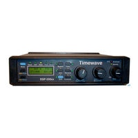
Timewave DSP-599zx Operating Manual (106 pages)
Audio Noise Reduction Filter
Brand:
Timewave
| Category:
Water Filtration Systems
| Size: 3 MB
Table of Contents
What Is Packed with Your DSP-599Zx
3
What Is Not Packed with Your DSP-599Zx that You will Need
3
Quick Start Setup
5
Table of Contents
7
Voice Mode
9
CW Mode
9
Data Mode
9
Introduction
11
Digital Signal Processing
11
DSP-599Zx Overview
11
Signal Flow
12
Front Panel Controls
13
Back Panel Connectors
14
Features Common to All Modes
15
Random/Tone Noise Reduction
15
Adaptive Multi-Tone and Manual Notch Filtering (Tone Noise Reduction)
15
Dual Channel Operation
15
Visible Memories
16
Automatic Gain Control
16
Bypass Control
17
Operating Modes
17
Voice Mode
18
Highpass/Lowpass Filters
18
Random Noise Reduction
18
Adaptive Multi-Tone and Manual Notch Filtering (Tone Noise Reduction)
19
CW Mode
19
Bandpass Filters
19
Random Noise Reduction
20
Manual Notch Filtering
20
Marker Tone
20
CW Tone Pitch Shift
20
Data Mode
21
Bandpass Filters
21
Data Tuning Function
22
Random Noise Reduction
22
RTTY Modem
22
RTTY Remodulator
22
RTTY FSK Test Signals
23
Test Instrument Mode
23
Audio Millivoltmeter
23
Audio Signal Generator
24
Two-Tone Generator
24
CTCSS Tone Decoder
24
Set-Up Mode
25
Installation
27
Power Supply
28
Connecting Cables
28
Wiring Information
28
DSP-599Zx Inputs and Outputs
28
Transceiver Speaker Output
29
External Speaker
29
Multimode Data Converter and Terminal Units (TU)
29
Transceiver PTT and T-R Outputs
29
Audio Input
30
Input Impedance Setup
30
Input Impedance Jumper Access
30
Audio Input Signal Level Setup
31
Audio Output
31
Headphone Jack
31
Headphone Volume Jumper Access
32
Speaker Outputs
33
Line Outputs
33
Input/Output Options
33
Speaker/Headphone
33
Line Output
34
PTT Input
35
RTTY Modem Input/Output
36
DIN Jacks - Radio a and Radio B
36
RS-232 Connector
36
Setup - Install
37
Audio Input Signal Level Setup
37
Line out Signal Level Setup
38
Speaker/Headphone Routing
39
Alternate Channel Gain
40
Line out Routing
41
Reset Memory
42
Exit Setup
42
General Operation
43
Introduction
43
Front Panel Operation
43
Controls Common to All Modes and Features
44
Primary Operating Modes [Mode]
44
Secondary Operating Modes and Features [Shift]
44
Speaker Control [Spkr/Chan]
44
Channel Control [Spkr/Chan]
45
Memory Operation [Rcl/Store]
45
User Selectable Power up Mode
47
Bypass [Bypass]
47
Automatic Gain Control [AGC]
47
Noise Reduction
48
Power Switch/Gain Adjust Control
48
Voice Mode
49
Operation
49
High Pass/Low Pass Filters
49
Noise Reduction
50
AM Line Noise
51
Heterodyne Elimination/Notch Filters
52
Automatic Notch Filter
52
Manual Notch Filter
53
Voice Bypass
54
Setup - Voice
54
AM Line Noise
55
Exit Setup
55
CW Mode
57
Operation
57
Bandpass Filters
57
Noise Reduction
58
Manual Notch Filter
58
CW Marker Tone
59
CW Tone Pitch Shift
59
CW Bypass Mode
60
Setup - CW
61
Marker Tone Level
61
Exit Setup
61
Introduction
63
Operations Common to All Data Types
63
Basic Data Mode Operation
63
Data Settings Display
64
Data Tuning Function
64
Random Noise Reduction
65
Data Bypass Mode
65
Data Filter Mode
66
RTTY, AMTOR, SITOR, Pactor, G-TOR
66
HF Packet
67
Clover
67
SSTV and Wefax
67
RTTY FSK Test Signals
67
RTTY Modem Operation
68
RTTY Remodulator Operation
69
Data Operating Hints
70
Data Primer
70
Frequency Shift
70
Center Frequency
70
Baud Rate
71
QRM Operating Hint
71
Mark Space Frequencies
71
Setup - Data Mode
72
Speaker Mute/Bypass
72
Modem Assignment
73
FSK Mark Control
73
Configuring Data Operating Modes
74
Exit Setup
76
Test Instrument Operation
77
Audio Millivoltmeter
77
Operation
78
Sine Wave Generator
79
Two-Tone Generator
80
CTCSS Decoder
81
Autodetect
81
Autodetect Display with Input CTCSS Tone
82
Tone Squelch
82
CTCSS Tone Squelch Selection
82
CTCSS Tone Squelch Detection
82
CTCSS Tone Squelch
83
CTCSS Tone Squelch Switch Output Jack and Pin Numbers
83
What Are CTCSS Tones
83
CTCSS Tone Frequencies - Hz
84
Setup - Test Instrument
84
Default CTCSS Tone
85
CTCSS Trigger Threshold
85
Signal Generator Calibration
86
Millivoltmeter Calibration
87
Exit Setup
88
Troubleshooting
89
Common Problems and Solutions
89
Nothing Comes on When I Turn on the Power
89
Normal" LED Does Not Flash on Audio Peaks
90
Overload" LED Flashes Constantly on Audio Peaks
90
No Audio Output
90
It Still Does Not Work
91
Specifications
93
Glossary
95
Product Warranty
97
Exclusive Remedies
97
Electromagnetic Interference
99
Schematic Diagrams
101
Advertisement
Timewave DSP-599zx Features (24 pages)
Audio Noise Reduction Filter
Brand:
Timewave
| Category:
Recording Equipment
| Size: 0 MB
Table of Contents
Front Panel
3
Back Panel
4
Voice Mode
6
Data Mode
6
DSP-599Zx Introduction
7
Digital Signal Processing
7
DSP-599Zx Overview
8
Signal Flow
9
Features Common to All Modes
10
Dual Channel Operation
10
Visible Memories
11
Automatic Gain Control
12
Bypass Control
12
Operating Modes
13
Bandpass Filters
15
Manual Notch Filtering
16
Marker Tone
16
CW Tone Pitch Shift
16
Test Instrument Mode
20
DSP-599Zx Specifications
22
Signal Processing
23
Timewave DSP-599zx Operation/Reference Card (2 pages)
Brand:
Timewave
| Category:
Signal Processors
| Size: 0 MB
Advertisement
Advertisement
Related Products
Timewave DSP-59Y
Timewave DSP-59+
Timewave DSP-9
Timewave DSP-232
Timewave DSP-D300
Timewave DM-1
Timewave DSP-9+
Timewave Categories
Controller
Noise Reduction Machine
Measuring Instruments
Water Filtration Systems
Modem
More Timewave Manuals
Login
Sign In
OR
Sign in with Facebook
Sign in with Google
Upload manual
Upload from disk
Upload from URL