Sign In
Upload
Manuals
Brands
ThermoFisher Scientific Manuals
Measuring Instruments
43iQHL
ThermoFisher Scientific 43iQHL Manuals
Manuals and User Guides for ThermoFisher Scientific 43iQHL. We have
1
ThermoFisher Scientific 43iQHL manual available for free PDF download: Instruction Manual
ThermoFisher Scientific 43iQHL Instruction Manual (278 pages)
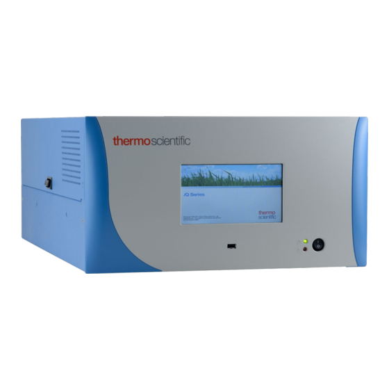
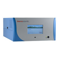
High Level Sulfur Dioxide Analyzer
Brand:
ThermoFisher Scientific
| Category:
Measuring Instruments
| Size: 15 MB
Table of Contents
Table of Contents
3
Chapter 1 Introduction
9
Iq Series Instrument Platform
10
Figure 1-1. 43Iqhl Front
10
43Iqhl Principle of Operation
11
Figure 1-2. 43Iqhl Flow Schematic
12
Figure 1-3. 43Iqhl Flow Schematic with Zero Span
12
Specifications
13
Table 1-1. 43Iqhl Specifications
13
Dimensions
15
Figure 1-4. Bench Mount Assembly (Dimensions in Inches [MM])
15
Figure 1-5. Rack Mount Assembly (Dimensions in Inches [MM])
16
Figure 1-6. Rack Mount Requirements
17
Installation and Setup
19
Unpacking and Inspection
19
Cover Removing and Replacing
20
Figure 2-1. Removing the Cover
20
Mounting Options
21
Bench Mount
21
Figure 2-2. Installing Feet
21
Rack Mount
22
Figure 2-3. Removing the Front Panel
22
Figure 2-4. Installing Ears and Handles
23
Setup Procedure
24
Figure 2-5. 43Iqhl Rear Panel
25
Figure 2-6. Atmospheric Dump Bypass Plumbing
25
Startup
26
Figure 2-7. Front Panel and Touchscreen Display
26
Chapter 3 Operation
27
Instrument Display
27
Main Menus and Keypads
31
Numeric Keypad
32
Alphanumeric Keypad
33
Calibration
35
Calibrate Background
37
Calibrate Span Coefficient
38
Zero/Span Schedule
40
Advanced Calibration
42
Manual Calibration
44
Multipoint Calibration
49
Calibration History
52
Data
53
View Data Log (Last Hour)
54
View Data Log (Last 24 Hours)
55
View Data Log (User Defined Time)
56
Advanced Data Setup
58
Data Logging Setup
59
Select Data Logging Variables
60
Streaming Data Setup
61
Select Streaming Variables
62
Settings
63
Health Check
64
Status and Alarms
65
Valve and Pump Resets
74
Predictive Diagnostics
80
Maintenance
81
Preventive Maintenance
82
Change Part
84
Maintenance History
85
Service Tips
86
File Sharing and Support
87
Iq360
88
Measurement Settings
91
Averaging Time
93
Range Mode Selection
95
Range Setting
97
Gas Mode
98
Gas Units
99
Advanced Measurement Settings
100
Communications
106
Wired TCP/DHCP
108
Analog I/O
111
Digital I/O
112
Email Server (SMTP)
113
Bayern Hessen Settings
114
Ethernet Protocol Selection
115
Instrument Settings
116
Display Setup
117
Alarm Setpoints
118
Clock
121
Time Zone
125
Configuration
128
Security Access Levels
129
Change Security to View Only Access
131
Change Full Access Security Password
132
Change Instrument Password
134
Reset Instrument Password
136
USB Drive
137
Firmware Update Via USB Drive
138
Download Data to USB Drive
142
Change USB Password
145
Reset USB Password
147
User Contact Information
148
Update Bootloader
149
Chapter 4 Calibration
151
Equipment Required
151
Zero Air Generation
152
Commercial Heatless Air Dryers
152
Figure 4-1. no Interference Data
152
Absorbing Column
153
SO 2 Concentration Standard
153
Calibration Gas Generation
153
Cylinder Gas Dilution
153
External Flow Meter(S) and Controller(S)
154
Figure 4-2. Cylinder Gas Dilution System
154
Commercial Precision Dilution Systems
155
Calibration
155
Calibration in Dual/Auto Range Mode
157
Zero and Span Check
160
Manual Calibration
161
Adjust Background
162
Adjust Span Coefficient
162
Multipoint Calibration
164
High and Low Multipoint Calibration
166
Calibration Frequency
166
Zero/Span Schedule
167
Next Time
167
Period
167
Zero/Span/Purge Duration Minutes
168
Schedule Averaging Time
168
Zero/Span Ratio
168
Chapter 5 Maintenance
169
Safety Precautions
169
Fan Filter Inspection and Cleaning
169
Pump Rebuilding
170
Figure 5-1. Single Stage Pump
170
Figure 5-2. Pump Rebuilding
172
Leak Test
173
Lamp Voltage Check
174
Lamp Voltage Adjustment
174
Chapter 6 Troubleshooting
177
Safety Precautions
177
Troubleshooting Guide
177
Table 6-1. 43Iqhl Troubleshooting Guide
177
Chapter 7 Servicing
185
Safety Precautions
185
Figure 7-1. Properly Grounded Antistatic Wrist Strap
186
Firmware Updates
187
Replacement Parts List
187
Figure 7-2. 43Iqhl Component Layout Top View
188
Figure 7-3. 43Iqhl Component Layout Side View
188
Fuse Replacement
189
Figure 7-4. Replacing the Fuses
189
Filter Replacement
190
Figure 7-5. Start with Top Right Corner of Fan Cover
190
Figure 7-6. Removing the Fan Cover
190
Figure 7-7. Unplugging the Fan Cable
191
Figure 7-8. Replacing the Fan
192
Measurement Side Removal and Replacing
193
Figure 7-9. Unplugging the Fan Cable
193
Figure 7-10. Unplugging the DMC Cable
194
Figure 7-11. Unfasten Hardware Front for Measurement Side Removal
195
Figure 7-12. Unfasten Hardware Rear for Measurement Side Removal
196
LCD Module Replacement
197
Figure 7-13. Replacing the LCD Module
197
Figure 7-14. Remove Electrical Cables from LCD
198
I/O Replacement
199
Figure 7-15. I/O Replacement, Arm
199
Figure 7-16. I/O Replacement, Remove Board
199
Figure 7-17. I/O Replacement, Install
200
Figure 7-18. I/O Replacement, Close Arm Alignment
200
Peripherals Support Board and System Controller Board Replacement
201
Figure 7-19. Replacing the Peripherals Support Board
201
DMC Pressure and Flow Board
202
Figure 7-20. Flow Pressure Board, Disconnect DMC Cable
202
Figure 7-21. Flow Pressure Board, Screws
203
Pump Replacement
204
Figure 7-22. Remove Pump, Disconnect and Unfasten
205
Figure 7-23. Pump Removal, Keyway
206
Figure 7-24. Pump Replacing, Unfasten Screws
206
Capillary Cleaning And/Or Replacement
207
Figure 7-25. Remove Capillary, Disconnect and Unfasten
207
Figure 7-26. Capillary Plate, Keyway
208
Figure 7-27. Capillary and O-Ring Replace
208
Capillary O-Ring Replacement
209
Power Supply Replacement
209
Figure 7-28. Removing Power Supply
210
Figure 7-29. Replacing Power Supply
210
Step POL Board Replacement
211
Figure 7-30. Unplug and Unfasten Step POL Board
211
Figure 7-31. Clear Partition Keyway Step POL Board
212
Figure 7-32. Step POL Board 1 Switch Settings
213
Figure 7-33. Optional Step POL Board 2 Switch Settings
213
DMC Optical Bench Removal
214
Optical Bench Assembly Removal
214
Figure 7-34. Removing the DMC Optical Bench Removal from Instrument
215
Optical Bench Assembly Removal
216
Figure 7-35. Removing the Optical Bench Assembly
216
Photomultiplier Tube (PMT) Replacement
218
Figure 7-37. Removing the PMT Assembly
218
Figure 7-38. Removing the PMT Cover
219
Figure 7-39. Replacing the PMT
219
Flasher Pack Replacement
220
Figure 7-40. Removing and Replacing the Flasher Pack
220
Flasher Pack Lamp Replacement
221
Figure 7-41. Replacing the Flasher Pack Lamp
221
Kicker Assembly Replacement
224
Figure 7-44. Removing and Replacing the Kicker Assembly
224
Optional Manifold Replacement
225
Figure 7-46. Replacing the Manifold Pt 2
226
Figure 7-47. Replacing the Manifold Pt 3
226
Auxiliary Sensor Replacement
227
Figure 7-48. Auxiliary Sensor Removal Pt 1
227
Figure 7-50. Replacing the Auxiliary Sensor
228
Chapter 8 System Description
229
Condensing Lens
230
Mirror Assembly
230
Light Baffle
230
Bandpass Filter
230
Flash Lamp Trigger Assembly
231
Flash Lamp
231
Flash Trigger Board
231
Flash Intensity Assembly
231
Photomultiplier Tube
231
Optical Bench DMC Board
231
Bench Heater
232
Common Electronics
232
Figure 8-1. Common System Interconnect Diagram
233
Figure 8-2. 43Iqhl System Interconnect Diagram
234
Power Supply
235
Front Panel
235
I/O and Communication Components
235
System Controller Board
235
Backplane Board
235
Peripherals Support System
236
Fan
236
Step POL Board
236
Sample Pump
236
Solenoid Valve Panel
236
Flow/Pressure DMC
236
Firmware
236
Chapter 9 Optional Equipment
239
Connecting External Devices
239
Figure 9-1. I/O Expansion Replacement Boards
239
Communication Board
240
RS-232/RS-485 Port
240
RS-485 External Accessory Port
240
Figure 9-2. RS-232/RS-485 Port
240
Table 9-1. RS-232/RS-485 Port Terminal Assignment
240
Figure 9-3. RS-485 External Accessory Port
241
Table 9-2. RS-485 External Accessory Port Terminal Assignment
241
Analog I/O Board
242
Analog Voltage Inputs
242
Figure 9-4. Analog Voltage Inputs
242
Table 9-3. Analog Voltage Inputs Assignment
242
Analog Voltage Outputs
243
Figure 9-5. Analog Voltage and Current
243
Analog Output Calibration
244
Table 9-4. Analog Voltage and Current Assignment
244
Analog Output Zero Calibration
245
Analog Output Full Scale Calibration
247
Digital I/O Board
249
Digital Inputs
249
Digital Relay Switches
249
Valve Driver Outputs
249
Figure 9-6. Digital Inputs
249
Table 9-5. Digital Inputs Terminal Assignment
250
Figure 9-7. Digital Relay Switches
251
Table 9-6. Digital Relay Switch Assignment
252
Figure 9-8. Valve Driver Outputs
253
Table 9-7. Valve Driver Outputs Assignment
254
Internal Zero/Span and Sample Valves
255
Heated Hydrocarbon Kicker
255
PTFE Particulate Filter
255
Appendix A Safety, Warranty, and WEEE
257
Safety
257
Safety and Equipment Damage Alerts
257
Warranty
258
WEEE Compliance
260
WEEE Symbol
260
Appendix B Quick Reference
261
List of Figures
261
GNU Lesser General Public License
265
Advertisement
Advertisement
Related Products
ThermoFisher Scientific Ozone Primary Standard 49iQPS
ThermoFisher Scientific Applied Biosystems Veriti 4375305
ThermoFisher Scientific Applied Biosystems Veriti 4375786
ThermoFisher Scientific Applied Biosystems Veriti 4388444
ThermoFisher Scientific Applied Biosystems Veriti 4384638
ThermoFisher Scientific Wellwash 4Mk2
ThermoFisher Scientific 4483636
ThermoFisher Scientific 4483638
ThermoFisher Scientific 44840714
ThermoFisher Scientific 4484073
ThermoFisher Scientific Categories
Laboratory Equipment
Measuring Instruments
Microscope
Data Loggers
Security Sensors
More ThermoFisher Scientific Manuals
Login
Sign In
OR
Sign in with Facebook
Sign in with Google
Upload manual
Upload from disk
Upload from URL