Sign In
Upload
Manuals
Brands
The Airplane Factory Manuals
Aircrafts
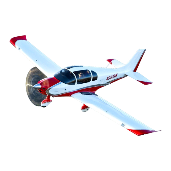
Sling 4
The Airplane Factory Sling 4 Manuals
Manuals and User Guides for The Airplane Factory Sling 4. We have
1
The Airplane Factory Sling 4 manual available for free PDF download: Maintenance Manual
The Airplane Factory Sling 4 Maintenance Manual (344 pages)
Plane
Brand:
The Airplane Factory
| Category:
Aircrafts
| Size: 5 MB
Table of Contents
Table of Contents
8
1 General
19
Description
19
Aircraft Specifications and Data
20
Aircraft 3-View Drawing
20
Aircraft Geometric Dimensions
21
Aircraft Weights
22
Engine
23
Approved Substances, Fluids, Lubricants and Capacities
24
Fastener Torque Values and Wrench Sizes
28
General
28
Specific
28
Equipment List
29
Tyre Specification and Pressures
30
Ground Handling
30
Jacking
31
Parking and Tie down
32
Aircraft Levelling
32
Longitudinal Levelling
33
Figure 1: Longitudinal Leveling Reference Position
34
Transverse Levelling
35
Figure 2: Transverse Leveling Reference Position
36
Aircraft Alignment
37
Figure 3: Aircraft Alignment
37
Control Surface Deflection / Travel
38
Rudder Control Cable Tension
38
Aircraft Rigging
39
Rudder Cable Tension Adjustment
39
Elevator Adjustment
39
Elevator Trim Tab Adjustment
39
Aileron Adjustment
39
Flap Adjustment
39
Weight and Balance Information
40
Requirement / Schedule
40
Moment Arms
40
Figure 4: Moment Arms
40
Centre of Gravity Formulae
41
Empty Weight Centre of Gravity Table
41
Empty Weight Centre of Gravity Determination
42
Corrosion Prevention
44
Aircraft Storage
46
Short Term Storage
46
Medium Long Term Storage
46
Outside Storage
47
Returning the Aircraft to Service
47
Sources for the Purchasing of Parts
48
Disposable Replacement Parts
48
Aircraft Placards and Equipment Labelling
49
Markings and Placards
49
2 Introduction
57
General Considerations Regarding Inspection
57
Inspection Panels
60
Inspection Schedule
61
Engine
61
Propeller
61
Airframe and Systems
61
Condition Inspection (100 Hour / Annually)
62
Inspection Panels and Initial Inspection and Cleaning
62
Fuselage Group
62
Cabin and Cockpit Group
62
Engine and Cowling Group
63
Landing Gear Group
63
Wing and Centre Section Assembly
64
Empennage Assembly
64
Propeller Group
64
Radio Group / Avionics / Electronic Equipment
65
Optional Equipment
65
Hour, 100 Hour and Annual Service Inspection Checklist
66
Lubrication Points, Lubricants and Intervals
80
Service Bulletins / Instructions / Letters
80
Service Schedule
80
Service Period Adjustment
81
Items with Calendar Based Servicing
82
Daily
83
As Needed
83
Date: 2014/11/10
83
First 25 Hours
83
First 50 Hours
84
Every 50 Hours / Annually
84
Every 100 Hours / Annually
85
4 Airframe
86
Wing
87
Main Wing Section
87
Wing Removal / Installation
88
Figure 5: Front Wing Spar to Fuselage Connection
91
Figure 6: Rear Wing Spar to Fuselage Connection
92
Figure 7: Aileron Pushrod-To-Control Stick Connection
92
Aileron(S )
94
Aileron Control System
94
Figure 8 : Aileron Control System
94
Aileron Removal / Installation
95
Figure 9: Aileron Hinge (Inboard)
97
Figure 10: Aileron Hinge (Outboard)
98
Figure 11: Aileron Pushrod -To-Bellcranck Connection
99
Aileron Adjustment
100
Figure 12: Aileron Adjustment - Cabin Side
101
Figure 13: Aileron Adjustment - Wing Side
102
Aileron Autopilot Servo / Servo Pushrod Removal / Installation
104
Figure 14: Autopilot Aileron Servo Installation
106
Figure 15: Aileron Autopilot Servo Pushrod - Control Stick / Torque Tube End
107
Flaps
108
Flap Control System
108
Figure 16: Flap Control System
108
Flap Removal / Installation
109
Figure 17: Flap Hinges
111
Figure 18: Flap Pushrod-To-Flap Connection
112
Figure 19: Flap Pushrod-To-Flap Torque Tube Control Arm Connection
114
Flap Adjustment
115
Flap Actuator Motor Removal / Installation
117
Figure 20: Flap Actuator Motor Removal
118
Figure 21: Flap Actuator Motor Installation
119
Empennage
120
Horizontal Tail and Elevator
120
Figure 22: Horizontal Tail and Elevator
120
Elevator Control System
121
Figure 23: Elevator Control System
121
Elevator Removal / Installation
122
Figure 24: Elevator Pushrod to Elevator Connection
124
Figure 25: Horizontal Stabilizer-To-Elevator Hinge
125
Horizontal Stabilizer Removal / Installation
126
Figure 26: Horizontal Stabilizer to Fuselage Attachment
128
Elevator Trim Tab Motor Removal / Installation
129
Elevator Adjustment
132
Figure 27: Elevator Adjustment
133
Elevator Trim Tab Adjustment
135
Elevator Autopilot Servo / Servo Pushrod Removal / Installation
137
Figure 28: Autopilot Elevator Servo Installation
139
Figure 29: Autopilot Elevator Servo Pushrod -Torque Tube End
140
Vertical Tail and Rudder
141
Figure 30: Vertical Tail and Rudder
141
Rudder Control System
142
Figure 31: Rudder Control System
142
Rudder Removal / Installation
143
Figure 32: Rudder to Vertical Stabilizer Hinge Connection
145
Figure 33: Rudder Cable Connection
146
Vertical Stabilizer Removal
147
DOCUMENT No.: REVISION
148
Figure 34: Vertical Stabilizer to Fuselage Connection
149
Rudder Pedal Adjustment
151
Rudder Cable Tension Adjustment
152
Figure 35 : Rudder Cable Tension Adjustment
153
Fuselage
155
Rear Fuselage
155
Centre Fuselage
156
Front Seat Removal and Installation
156
Rear Seat Removal and Installation
158
Canopy and Windshield Cleaning
160
Upholstery Cleaning
160
Forward Fuselage and Firewall
161
Landing Gear
162
Main Gear
162
Figure 36: Main Landing Gear
162
Main Wheel Fairing Removal / Installation
163
Main Wheel Removal / Installation
165
Main Wheel Axle and Brake Mechanism Removal
168
Figure 37: Main Wheel Axle Installation
171
Main Wheel Disassembly / Assembly
172
Main Wheel Bearing Removal / Installation and Lubrication
175
Main Gear Removal / Installation
176
Figure 38: Main Gear Installation
179
Nose Gear
180
Figure 39: Nose Gear
180
Nose Wheel Fairing Removal / Installation
181
Nose Wheel Removal / Installation
182
Figure 40: Nose Wheel Installation
184
Nose Wheel Disassembly / Assembly
185
Figure 41: Front Wheel Hub Assembly
187
Nose Wheel Bearing Removal / Replacement
188
Nose Gear Removal / Installation
189
Figure 42: Nose Gear Installation
191
5 Power Plant
192
Cowling
192
Figure 43: Engine Cowling
192
Cowling Removal / Installation
193
Engine
196
General Maintenance and Servicing
196
Carburettor Synchronisation
196
Replacing Engine Oil
196
Replacing Engine Coolant
196
Spark Plug Replacement
196
Verifying Engine Oil Level
197
Air Filter Removal, Cleaning and Replacement
198
Muffler / Heat Exchanger Assembly Removal / Replacement
201
Muffler / Heat Exchanger Disassembly / Assembly
203
Removal / Installation of Oil and Coolant Radiators
205
Oil Cooler / Radiator Pipe Connection / Disconnection
206
Coolant Radiator Pipe Connection / Disconnection
209
Engine Removal / Installation
211
Figure 44: Engine Removal
215
Figure 45: Engine Installation
216
Engine Control System (Throttle and Choke)
218
Throttle Lever Friction Adjustment
219
Throttle Lever Friction Disc Replacement
220
Figure 46: Throttle Lever Friction Disc Installation
221
Propeller
222
General Maintenance and Service
222
Propeller Hub and Propeller Extension Torque Pattern
222
Figure 47: Propeller Installation / Propeller Extension Installation Torque Pattern
222
Spinner Removal / Replacement
223
General Considerations When Fitting Propeller Extension to Engine Flange
225
Propeller Removal / Installation
226
Figure 48: Airmaster Propeller Installation (Standard)
229
Figure 49: Airmaster Propeller Signal Wire to Slip-Ring Disc Connection (Vacuum Pump Fitted)
232
Figure 50: Airmaster Propeller Installation (Vacuum Pump Fitted)
233
Figure 51: Propeller Installation (External Alternator Fitted)
234
Propeller Assembly / Disassembly
235
Propeller Adjustment / Set-Up
237
Propeller Balancing
237
6 Fuel System
238
Figure 52: Fuel System
238
General Service Information and Considerations
240
Fuel Filter Replacement
241
Fuel Selector Unit Removal / Installation
243
Figure 53: Fuel Selector Unit Installation
245
Fuel Selector Unit Assembly / Disassembly
246
Figure 54: Fuel Selector Port Allocation and Fitting Orientation
247
Figure 55: Fuel Selector Fuel Fitting Alignment
247
Fuel Pump Assembly Removal / Installation
248
Fuel Pump Removal / Installation from / into Fuel Pump Assembly
254
Fuel Tank Leak Repair
256
Fuel Tank Drain Removal / Installation (Draining Wing Tank)
257
Figure 56: Wing Tank Fuel Drain Installation
258
Fuel Level Sender Assembly Removal / Installation (from / to Fuel Tank)
259
Figure 57: Fuel Sender Installation into Fuel Tank
262
Replacing Fuel Level Sender Assembly Sensor
263
Figure 58: Fuel Level Sender Assembly Sensor Replacement
266
Finger Strainer (on Fuel Pick-Up) Inspection
267
7 Avionics and Instruments
269
Figure 59: Standard Instrument Panel (Refer to Key on Next Page)
269
General Maintenance and Service of Instruments
270
Removal / Installation of Instrument Panel and Instruments
271
Pitot and Static Systems
273
Figure 60: Representative Pitot and Static System
273
Pitot System Leak Test
274
Static System Leak Test
275
Pitot and / or Static System Cleaning and Servicing
276
Ahrs and Compass
277
Ahrs and / or Compass Sensor Removal / Installation
277
Headphone Sockets
279
Headphone Socket Removal / Installation
279
Figure 61: Headphone Socket Installation
280
Antennae
281
Date: 2014/11/10
281
Vhf Communication Antenna
281
Vhf Antenna Removal / Installation
281
Figure 62: VHF Antenna Installation
282
Gps Antenna
283
Gps Antenna Removal / Installation
283
8 Utility Systems
285
Cabin Heating and Cooling
285
Heat Exchanger Assembly Removal and Installation
285
9 Brake System
286
Figure 63: Brake System
286
Brake Fluid Draining, Replacement and Brake System Bleeding
287
Brake Mechanism Removal / Installation
289
Brake Disc Replacement
290
Brake Lining Replacement
291
10 Electrical System
294
Figure 64: Electrical System (Overview)
294
Battery Removal / Installation
296
Efis Back-Up Battery Removal / Installation
298
Alternator Maintenance
300
Replacement of Circuit Breakers and / or Switches
300
Regulator / Rectifier Removal and Replacement
303
11 Exterior Lighting
305
Navigation Lights
305
Navigation Light Removal / Installation
306
Landing and Taxi Lights
308
Landing and / or Taxi Light Removal / Installation
308
Figure 65 : Landing and Taxi Light Installation
310
Landing and / or Taxi Light Replacement
311
Landing and / or Taxi Light Adjustment
313
Strobe Light
314
Strobe Light Removal / Installation
314
12 Emergency and Safety Systems
316
Ballistic Parachute
316
General Service and Maintenance
316
Safety Harnesses
317
Removal / Installation of Front Occupant Safety Harness(Es)
317
Removal / Installation of Rear Occupant Safety Harness(Es)
320
13 Appendix A (Avionics and Electrical System Wiring Diagrams)
321
Charge and Start System / Fuel Pumps Wiring Diagram
321
Figure 66: Charge and Start System Wiring Diagram /Fuel Pump Wiring
321
Switches and Circuit Breakers Wiring Diagram
322
Figure 67: Switches and Circuit Breakers Wiring Diagram
322
External Alternator Wiring Diagram
323
Figure 68: External Alternator Wiring Diagram
323
Flap System Wiring Diagram
324
Figure 69: MGL SP 10 Flap / Trim Controller Wiring Diagram
324
Inotec
325
Figure 70: Flap System Wiring Diagram - INOTEC
325
E-Flaps
326
Figure 71: Flap System Wiring Diagram - E-Flaps
326
Elevator Trim Motor Wiring Diagram
327
Dual Stick Trim
327
Figure 72: Elevator Trim Motor Wiring Diagram - Dual Control Sticks
327
Single Stick Trim
328
Figure 73: Elevator Trim Motor Wiring Diagram - Single Control Stick
328
Efis System / Communications Bus Layout
329
Figure 74: EFIS System / Communications Bus Layout
329
Ahrs and Compass Wiring Diagram
330
Figure 75: AHRS and Compass Wiring Diagram
330
Autopilot Roll Servo and Pitch Servo Wiring Diagram
331
Figure 76: Autopilot Roll Servo and Pitch Servo Wiring Diagram
331
Efis Back-Up Battery Charge Circuit
332
Figure 77: EFIS Back-Up Battery Charge Circuit
332
Headphone / Radio / Intercom Wiring Diagram
333
Garmin Gtr 200 Radio
333
Figure 78: Headphone / Radio (GARMIN GTR 200) / Intercom Wiring Diagram
333
Garmin Gtr 225 Radio
334
Figure 79: Headphone / Radio (GARMIN GTR 225) / Intercom Wiring Diagram
334
Position / Navigation Lights Wiring Diagram
335
Figure 80: Position / Navigation Lights Wiring Diagram
335
Rdac to Oil Pressure Transducer Wiring Diagram
336
Figure 81: RDAC to Oil Pressure Transducer Wiring Diagram and Settings
336
Dual Efis Installation Wiring Diagram
337
Figure 82:Dual EFIS Installation
337
Transponder Wiring Diagram
338
Trig Tt21 Transponder Wiring Diagram
338
Figure 83: TRIG TT21 Transponder Wiring Diagram
338
Sandia Stx 165R Transponder Wiring Diagram
339
Figure 84: SANDIA STX 165R Transponder Wiring Diagram
339
Engine Monitoring Transducers (Sensors) / Rdac Electrical Wiring
340
Efis and Ibox Electrical Wiring
340
Propeller and Propeller Controller Electrical Wiring Information
340
Rotax 914 Ul Engine Electrical Wiring Information
340
14 Appendix B (Firewall Mounted Equipment)
341
Figure 85: Firewall Mounted Equipment
341
15 Appendix C (General Procedures and Techniques Not Described Elsewhere)
342
Removal of Two-Ear Clamps
342
Pushrod Adjustment
342
Figure 86: Two-Ear Clamp Removal
342
Figure 87: Pushrod Adjustment
342
Fitting of Fire Resistant Sleeving
343
16 Appendix D (an Washer and Nut Hardware Designations)
344
Advertisement
Advertisement
Related Products
The Airplane Factory Categories
Aircrafts
More The Airplane Factory Manuals
Login
Sign In
OR
Sign in with Facebook
Sign in with Google
Upload manual
Upload from disk
Upload from URL