Sign In
Upload
Manuals
Brands
Thales Manuals
Radio
AN/PRC-148V
Thales AN/PRC-148V Manuals
Manuals and User Guides for Thales AN/PRC-148V. We have
1
Thales AN/PRC-148V manual available for free PDF download: Operation And Maintenance Instructions With Illustrated Parts Breakdown
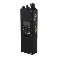
Thales AN/PRC-148V Operation And Maintenance Instructions With Illustrated Parts Breakdown (102 pages)
MULTIBAND INTER/INTRA TEAM RADIO
Brand:
Thales
| Category:
Radio
| Size: 1 MB
Table of Contents
Table of Contents
3
List of Figures
6
Safety Summary
9
Foreword
10
Mbitr Unit
12
Chapter 1 General Information
13
Mbitr Description
13
Receiver-Transmitter Unit
13
Table 1-1 Physical Characteristics
13
Batteries
14
Holster and Accessory Carrying Bag
14
Antennas
14
Audio/Keyfill Adapter Device
15
Accessories
15
Audio Accessories
15
Antennas
16
Vehicle Adapter
16
Special Power Adapter Interface (SPAI)
16
Battery Chargers
16
PC-Based Radio Programmer
16
Cables
17
Transceiver Characteristics
18
Transmitter Characteristics
18
1.3.2 Receiver Characteristics
18
Communication Security (Comsec)
18
Table 1-2 Continuous Tone Controlled Squelch System (CTCSS) Available Tones (in Hz)
18
Compatibility
19
Tone Squelch Disable
19
Encryption Device Keying
19
Tempest
19
Algorithms
19
Cryptographic Key Storage
19
Zeroization
19
Key Retention
19
Fade Bridging
19
1.4.10 Initial Synchronization
20
Sincgars Transmission Security (Transec)
20
Frequency Range
20
Operating Modes
20
Squelch Tones
20
SINCGARS Electronic Counter Counter-Measures (ECCM) Remote Fill (ERF)
20
Encryption Device Keying
20
Havequick I/II Transmission Security
21
Frequency Range
21
Interoperability
21
Over-The-Air Time of Day
21
Squelch Tones
21
COMSEC Compatibility
21
Net Support
21
Andvt Operation
21
Frequency Range
22
Channel Bandwidth
22
Interoperability
22
Operating Modes
22
Chapter 2 Operating Instructions
23
Controls, Indicators, and Connectors
23
Controls
23
Mbitr Keypad
23
Table 2-1 Key Assignments Table
23
Mbitr Controls and Connectors
24
2.1.2 Indicators
25
2.1.3 Connectors
25
Mbitr Controls and Connectors
26
Operating Procedures
27
2.2.1 MBITR Channels and Groups
27
Display Menus
27
Figure 2-5 Default Display Screen
28
Figure 2-6 Basic Alternate Default Display
28
Sincgars Alternate Display (Sc)
29
Sincgars Alternate Display (Fh)
29
Havequick Sc Alternate Display
29
Havequick Fh Alternate Display
29
Andvt Alternate Display
30
Figure 2-12 Receive Screen
30
Figure 2-13 Transmit Screen
30
Figure 2-14 Squelch Adjust Screen
30
Figure 2-15 Mode Select Screen
31
Figure 2-16 Emergency Beacon Select
31
PROGRAMMING Menu
32
Gps Transmit
32
Figure 2-18 Group Select Screen
32
Figure 2-19 Main Menu Screen
32
Figure 2-20 Initial Zeroize Screen
32
Clear All Screen
33
Comsec Zeroize
33
Comsec Zeroize All
33
Comsec Selective Zeroize
33
Transec Zeroize Screen
34
Figure 2-26 Radio Parameters Zeroize Screen
34
Figure 2-27 Key Fill Main Screen
34
Comsec Keyfill
35
Transec Fill Screen
36
Mode 2/3 Key Fill
36
Tod Selection Screen
37
Tod Fill Screen
37
Tod Rx Screen
37
Tod Tx Screen
37
Mwod-A Screen
37
Mwod-M Screen
38
Opr Day Screen
38
Wod Fill Screen
38
Fmt Fill Screen
39
Figure 2-43 Lockout Set Erf
40
Figure 2-44 Hopset Erf
40
Figure 2-45 Initial Programming Screen
41
Figure 2-46 Restricted Access Screen
41
Figure 2-47 Global Programming Screen
41
Figure 2-48 Transmit Timeout Screen
42
Figure 2-49 Backlight Timeout Screen
42
Figure 2-50 Set Clock Screen
42
Figure 2-51 Side Connector Enable
42
Figure 2-57 Group Programming Screen
48
Table 2-6 Group Options
48
Figure 2-59 Emergency Programming Screen
49
Figure 2-60 Beacon Programming
49
Figure 2-61 Radio Maintenance Screen
49
Figure 2-62 Built-In-Test Screen
49
Figure 2-63 Check Clock Screen
49
Scan
50
Figure 2-64 Display Elapsed Time Screen
50
Figure 2-65 Options Enabled Screen
50
Figure 2-67 Active Scan Screen
51
Figure 2-68 Priority Channel Assignment
51
Figure 2-69 Select Scan Plan
52
Figure 2-70 Configure Scan Screen
52
2.2.5 Cloning Operation
53
Digital Data Operation
54
Figure 2-71 Data Operation Screen
54
Expedient Retransmission
55
Chapter 3 Principles of Operation
57
General
57
Functional System(S) Operation
57
Figure 3-1 Radio Set, Simplified Block Diagram
57
Transceiver Module
58
Control/Crypto CCA
58
Radio Systems Module
58
Rechargeable Lithium Ion Battery
59
Non-Rechargeable Battery Holder
59
Mhz Transceiver Module
59
3.3.1 Receiver/Synthesizer CCA
60
Transmit CCA
60
Figure 3-2 Transceiver Module Block Diagram
61
Control/Crypto Circuit Card Assembly (CCA)
62
Microcontroller
62
Cryptographic Module
62
Red Dsp
62
Black Dsp
62
Figure 3-3 Control/Crypto Block Diagram
63
Fpga
64
Power Management
64
Front Panel Cca
64
Figure 3-4 Front Panel Block Diagram
65
Chassis Assembly
66
Chapter 4 Maintenance
67
General
67
Operational Checkout
67
Radio Preventive Maintenance
67
Battery Preventive Maintenance
67
Table 4-1 Built -I N Test Results
67
Troubleshooting
68
Table 4-2 Operator Troubleshooting Guide
68
Removal/Replacement Procedures - Operator
70
Audio Accessory Removal/Replacement (Urban Version)
70
Audio Accessory Removal/Replacement (Maritime Version)
71
Antenna Removal/Replacement
71
Battery Removal/Replacement
71
Watertight Integrity
72
Chapter 5 Illustrated Parts Breakdown
73
General
73
Maintenance Parts List
73
Numerical Index
74
Electrostatic Discharge (Esd) Sensitive Devices
75
Cage Code Summary
75
Figure 5-1 Multiband Inter/Intra Team Radio System (AN/PRC-148(V)(C))
78
Table 5-2 Multiband Inter/Intra Team Radio System, 20 Meter (AN/PRC-148 (V)1(C))
79
Table 5-3 Multiband Inter/Intra Team Radio System, 2 Meter (AN/PRC-148 (V)2(C))
80
Chapter 6 Mbitr Vehicle Adapter
85
General
85
Physical Characteristics
85
Equipment Description
85
Weight
86
Dimensions
86
Temperature
86
Electrical Characteristics
86
Installation
86
Mechanical Installation
86
Electrical Connections
86
Operation
86
Maintenance
87
Illustrations
87
Parts List
87
Figure 6-1 Rch
87
Figure 6-2 Mbitr Vehicle Adapter
87
Table 6-1 Parts List, MA6943
87
Chapter 7 Special Power Adapter Interface (Spai)
89
General
89
Physical Characteristics
89
Electrical Characteristics
89
Electrical Protection
89
Operation
90
Indicators
90
Performance
91
Chapter 8 Battery Chargers
93
General
93
Physical Characteristics
93
Weight and Dimensions
93
Temperature
93
Electrical Characteristics
93
Single Unit Charger
93
Table 8-1 Battery Charger Weights and Dimensions
93
Table 8-2 Operating and Storage Temperatures
93
Six (6) Unit Chargers
94
Performance
94
Operating Indications
94
Table 8-3 Charger Performance
94
Table 8-4 Charge Status Indicators
94
Illustrations
96
Chapter 9 Definitions
97
Definitions
97
Active Channel
97
Channel
97
CTCSS Tone
97
Electronic Remote Fill
97
Fade Bridge
97
Hopset
97
Initial Synchronization
97
Lockout Set
97
9.1.11 Open Channel
98
9.1.12 Priority Scan
98
9.1.13 Repeater Delay
98
9.1.14 Scan Revert Channel
98
9.1.15 Selected Channel
98
Time of Day (TOD)
98
9.1.17 Transmit (TX) Timeout
98
Word of Day (WOD)
98
9.1.19 Working Group
98
Index
99
Advertisement
Advertisement
Related Products
Thales AN/PRC-148
Thales AN/PRC-148C
Thales AHV1600
Thales Gemalto AHS3-E
Thales Gemalto AHS3-W
Thales Gemalto ALS3-E
Thales Gemalto ALS3-US
Thales Gemalto ALS3-C
Thales Gemalto ALAS5
Thales AS 680
Thales Categories
Network Hardware
GPS
Turntable
Server
Security System
More Thales Manuals
Login
Sign In
OR
Sign in with Facebook
Sign in with Google
Upload manual
Upload from disk
Upload from URL