Sign In
Upload
Manuals
Brands
Textron Manuals
Offroad Vehicle
Stampede 900 2017
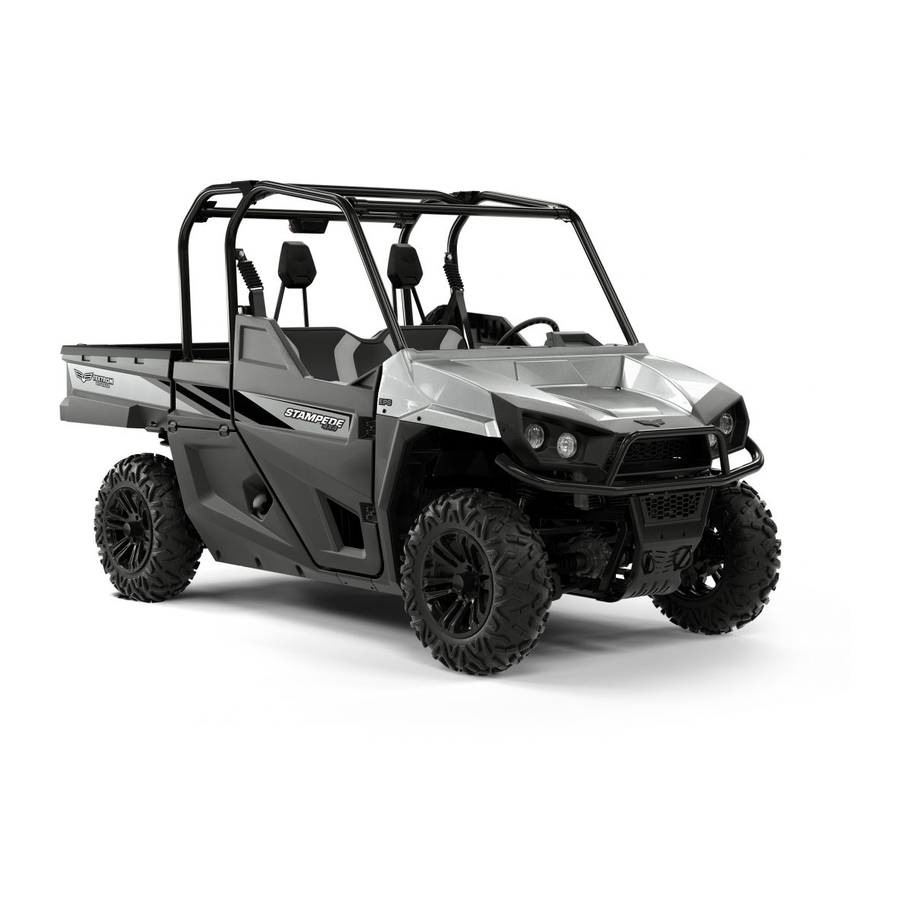
Textron Stampede 900 2017 Manuals
Manuals and User Guides for Textron Stampede 900 2017. We have
1
Textron Stampede 900 2017 manual available for free PDF download: Repair And Service Manual
Textron Stampede 900 2017 Repair And Service Manual (237 pages)
4x4 all terrain vehicle
Brand:
Textron
| Category:
Offroad Vehicle
| Size: 59 MB
Table of Contents
General Information & Routine Maintenance
13
Safety Information
5
General
5
General Operation
5
Maintenance
6
Ventilation
6
General Information and Routine Maintenance
7
Serial Number and Vin Location
7
Starting the Vehicle with a Discharged Battery
8
Routine Maintenance
8
Powertrain Maintenance
8
Brakes
8
CHART be Performed (See Fig
8
Tires
9
Light Bulb Replacement
9
Care and Cleaning of Vehicle
9
Polishing the Vehicle
9
Canopy and Windshield
9
Transporting the Vehicle
10
Prolonged Storage
10
Battery
10
Table of Contents
13
Engine
18
Safety
23
Important Safety Warning
23
Modifications to Vehicle
23
General Maintenance
23
Before Servicing the Vehicle
23
Lifting the Vehicle
25
Lifting Front of Vehicle
25
Lifting Rear of Vehicle
25
Lowering Vehicle
25
Body
27
General
27
Painting
27
Repairing Scratches
27
Complete Panel Repair
27
Decal Replacement
27
Cowl Removal
28
Standard Brush Guard Removal
30
Premium Brush Guard Removal
31
Rocker Panel Removal
32
Side Panel and Rear Fender Liner Removal
32
Quarter Panel and Front Fender Liner Removal
32
Door Removal
33
Door Handle and Latch Assembly Removal
34
Striker Plate Removal
35
Floorboards
35
Seating
36
Seat Bottom Removal
37
Seat Back Removal
37
Seat Closeout Removal
37
Extended Cab
38
Cargo Tray Removal
39
Rear Closeout Panel Removal
39
Front Closeout Panel Removal
39
Extended Cab Door Removal
39
Skid Plate Removal
40
Frame
43
General
44
Door Hinge Removal
44
Dash Support Removal
44
Hand Hold Removal
45
Front Shock Tower Brace Removal
45
Rear Shock Tower Brace Removal
45
Seat Frame Removal
47
B-Pillar Crossmember Removal
47
Rollover Protection System (Rops)
50
Removing the ROPS as a Complete Unit
50
Installing Rops Components
50
ROPS Side Tube Installation
50
ROPS Extended Cab Tubes Installation
50
Rear Cross-Tube Installation
50
Front Cross-Tube Installation
52
Seat Back Support Installation
52
Tighten ROPS Hardware
52
Seatbelt Installation
53
Headrest Installation
54
Truck Bed
58
Truck Bed Removal
58
Decal Replacement
59
Weather Protection
61
General
61
Canopy
61
Installing Mounting Brackets
61
Installing Canopy Clamps
62
Installing the Canopy
63
Wheels and Tires
65
Wheel and Tire Service
65
Tire Tread Depth
66
Tire Repair
66
Tire Replacement
66
Wheel Removal
66
Wheel Installation
66
Brakes
69
Maintenance
70
Daily Brake Performance Test
70
Brake System Inspection
70
Brake Fluid
70
Master Cylinder
71
Master Cylinder Replacement
71
Brake Pad Replacement
72
Rotor Replacement
73
Bleeding and Flushing
74
Bleeding
74
Bleeding Sequence
74
Flushing the Brake System
75
Brake and Accelerator Pedals
75
Brake Pedal Removal and Installation
75
Accelerator Pedal Removal
76
Front CV Shaft, Suspension and Steering
80
Front Suspension
80
Maintenance
80
Wheel Bearing Test
80
Front Hub Removal
80
Front Spindle Removal
81
Front Axle
83
CV Shaft Replacement
83
CV Joint Boot Replacement
83
Front Strut Assembly Replacement
83
Lower Control Arm Assembly Replacement
84
Front CV Shaft, Suspension and Steering
85
Remove the Front Spindle. See Front Spindle Removal
85
Stabilizer Bar Removal
86
Upper Control Arm Assembly Replacement
85
Front Differential
86
Front Differential Oil Check
86
Each Side of the Lower Control Arm to the Vehicle
86
Front Differential Oil Replacement
87
Front Differential Replacement
87
Remove the Front Wheel. See Wheel Removal on
87
Steering
88
Steering Wheel Replacement
90
Steering Column Removal
91
Steering Shaft Replacement (Non-EPAS)
91
Electric Power Assist System (EPAS) (if Equipped)
92
Steering Rack Replacement
93
Rack Ball Joint Replacement
93
Frame (Ref. Fig. 16)
93
Maintenance
94
Wheel Alignment
94
Ride Height Adjustment
95
Steering Wheel
95
Rear Axle and Suspension
97
Rear Suspension
98
Maintenance
98
Wheel Bearing Test
98
Hub Removal
98
Remove the Brake Calipers from the Rotor. See Brake Pad Replacement
98
Rear Spindle Removal
99
CV Shaft Replacement
100
CV Joint Boot Replacement
100
Rear Strut Assembly Replacement
101
Lower Control Arm Assembly Replacement
101
Rear Axle and Suspension
102
Item Torque Specification
102
Ft. Lbs. (54 - 60 Nm)
102
Installation of Lower Control Arm Assembly Is the Reverse of Removal
102
Remove the Nuts (20) and Bolts (7) that Secure each
102
Stabilizer Bar Removal
102
Tighten the Hardware to the Torque Values Specified below
102
Upper Control Arm Assembly Replacement
102
Tool List Qty
102
Wheel Chocks
102
Ft. Lbs. (54 - 60 Nm)
103
Ft. Lbs. (95 - 105 Nm)
103
Installation of Upper Control Arm Assembly Is the
103
Ratchet
103
Rear Differential
103
Oil Change
103
Rear Differential Oil Check
103
Rear Differential Oil Replacement (Upper Chamber)
103
Tighten the Hardware to the Torque Values Specified
103
Torque Wrench, Ft. Lbs
103
Rear Differential Oil Replacement (Lower Chamber)
104
Rear Differential Replacement
105
Floor Jack
105
Adjusting the Shift Lever Cable
108
Continuously Variable Transmission (Cvt)
111
General
111
Clutches
111
Primary Clutch
111
Secondary Clutch
111
Increased Load
111
Equilibrium
111
Cvt Belt
113
CVT Belt Break-In
113
CVT Belt Inspection
113
CVT Belt Replacement
113
Primary Clutch Removal
113
Primary Clutch Installation
114
Secondary Clutch Removal
115
Secondary Clutch Installation
115
Draining the CVT
115
Prop-Shaft
117
General
118
Prop-Shaft Maintenance
118
Prop-Shaft Removal
118
11. Tighten the Hardware to the Torque Values Specified
119
Item Torque Specification
119
Engine
121
General
122
Engine Description
122
Engine Specifications
122
Engine Break-In
122
Engine Maintenance
122
Engine Oil
122
Engine Oil Type and Capacity
122
Checking the Engine Oil Level
122
Tool List Qty
122
Changing Engine Oil and Filter
123
Remove Engine Oil
123
Socket, 15Mm
123
Ratchet
123
Replace the Oil Filter
124
Refill Engine Oil
124
Air Filter Maintenance
124
Spark Plugs
125
Spark Plug Inspection and Replacement
125
Torque Wrench, Ft. Lbs
125
Engine Compression Test
126
Engine Removal
127
Exhaust System Removal
129
Air Intake
133
Engine Air Intake
134
Air Filter Maintenance
134
Air Filter Housing Removal
134
Cooling System
137
Cooling System
138
Coolant
138
Reservoir Coolant Level
138
Radiator Coolant Level
138
Coolant Replacement
139
Coolant Reservoir Removal
139
Radiator and Cooling Fan
139
Radiator Removal
140
Thermostat and Water Pump
141
Fuel System
144
General
144
Fuel
144
Fuel System Service
144
Fuel Tank Removal
144
Fuel Pump Assembly
145
Electrical System
147
Main Harness
147
Power Supply
147
Circuits and Controls
147
Testing Engine Starting Circuit
147
Voltage Test for Battery
148
Battery
148
Battery Cleaning
148
Battery Charging
148
Battery Storage
148
Battery Removal
149
Lights
149
Headlight Bulb Replacement
149
Headlight Beam Adjustment
150
Brake Light Bulb Replacement
150
Information Display Removal
151
Engine Control Unit (ECU)
151
Voltage Regulator Removal
155
Solenoid Controller Removal
155
Wiring Diagrams
156
Fault Testing
167
General
167
Voltmeter
167
Continuity Check
167
Testing a Switch for Continuity
167
Testing the Ignition System
167
Testing Fuses
167
Powertrain Performance
168
Starter Fault Testing
170
Suspension and Steering Fault Testing
170
General Specifications
174
General Specifications
175
General Specifications
176
Scheduled Maintenance
177
Initial Service Requirements
177
Severe Use Conditions
177
Scheduled Maintenance Chart
178
Recommended Lubricants and Fluids
180
Replacement of Maintenance Items
180
Fault Codes
183
Diagnostic Manual
183
Appendix A
183
Appendix A
184
Epas Fault Codes
185
Appendix A
186
Can
187
Appendix A
187
Appendix A
188
Table of Contents
192
1 About this Document
193
1.1 Meaning of the Symbols and Signal Words
193
1.2 Change Management
193
2 Safety
194
2.1 Meaning of the Safety Alert Symbol and Signal Words
194
2.2 Important Safety Messages
195
3 Tools and Accessories
197
3.1 Textron Motors Diagnostic Case
197
3.2 Equipment Workshop
197
4 Lights in Vehicle
198
4.1 Oil Pressure Warning Light
198
4.2 Temperature Warning Light
198
Malfunction Indicator Light (MIL)
199
5 Troubleshooting with Trouble Codes
200
5.1 Displaying Trouble Codes
200
5.2 Description of Trouble Codes
201
6 Test Procedures at Engine
221
6.1 Checking Voltage Regulator
221
6.2 Checking Generator
222
6.3 Checking Crankshaft Reluctor
223
6.4 Checking Thermostat
224
6.5 Checking Cam Spike at Rocker Arm
225
6.6 Checking Oil Pressure
226
6.6.1 Troubleshooting Guide too Low Oil Pressure
227
6.6.2 Troubleshooting Guide too High Oil Pressure
227
7 Components Overview
228
Appendix
234
Overview of Revisions
234
Index
235
Advertisement
Advertisement
Related Products
Textron Bunton EC Hydro Midsize 930024
Textron Ransomes 933303H
Textron RANSOMES 933506
Textron Greenlee 915FS
Textron Greenlee 960 PS Series
Textron RANSOMES 933304J
Textron BOB-CAT 930023
Textron JACOBSEN BOB-CAT 930322A
Textron JACOBSEN BOB-CAT 930323A
Textron JACOBSEN BOB-CAT 930324A
Textron Categories
Lawn Mower
Crimp tool
Power Tool
Cutter
Measuring Instruments
More Textron Manuals
Login
Sign In
OR
Sign in with Facebook
Sign in with Google
Upload manual
Upload from disk
Upload from URL