Sign In
Upload
Manuals
Brands
Textron Manuals
Lawn Mower
JACOBSEN R-311 69166
Textron JACOBSEN R-311 69166 Manuals
Manuals and User Guides for Textron JACOBSEN R-311 69166. We have
1
Textron JACOBSEN R-311 69166 manual available for free PDF download: Technical/Repair Manual
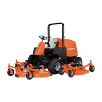
Textron JACOBSEN R-311 69166 Technical/Repair Manual (402 pages)
Brand:
Textron
| Category:
Lawn Mower
| Size: 36.81 MB
Table of Contents
Table of Contents
8
Introduction
9
Prepare for the Job
9
Safety Notices
9
Safety Label Locations
9
Inspect Safety Labels
13
Keep Work Area Clean
13
Keep Work Area Well Ventilated
13
Use Proper Eye and Face Protection
13
Park Mower Safely
13
Use Lifting Equipment Safely
14
Support Machine Securely
14
Use Compressed Air and Air Tools Safely
14
Service Tires Safely
15
Handle Fuel Safely
15
Store Volatile and Hazardous Materials Safely
15
Handle Chemical Products Safely
16
Service Hydraulic System Safely
16
Service Cooling System Safely
16
Service Electrical Components Safely
17
Dispose of Waste Materials Safely
17
Mower Identification
19
Serial Number
19
Engine Serial Number
20
Optional Machine Accessories
20
Component Location
21
Specifications
23
Quick Reference Specifications
23
Specifications
31
General Engine Specifications
31
Repair Specifications
31
Component Location
32
Kubota V2203-M-E3B
32
Checks and Adjustments
34
Throttle Cable
34
Purging the Fuel System
35
Repair
36
Fan Belt
36
Air Cleaner Assembly
37
Muffler
37
Exhaust Manifold
38
Radiator/Oil Coolers
39
Thermostat
43
Throttle Cable and Control Lever
44
Fuel Filter
45
Fuel Pump
46
Engine
47
Engine Service
50
Specifications
55
Test and Adjustment Specifications
55
Theory and Diagnostic Information
56
Electrical Component Symbols
56
Electrical Schematic Component Identification
59
Electrical Schematic
61
Theory of Operation and Sub-Circuit Schematics
69
Power Circuit-Theory of Operation
69
Power Circuit Schematic
70
Glow Plug Circuit-Theory of Operation
77
Glow Plug Circuit Schematic
78
Start Circuit-Theory of Operation
79
Start Circuit Schematic
80
Run Circuit-Theory of Operation
81
Run Circuit Schematic-On Seat
82
Run Circuit Schematic-Off Seat
83
Charging Circuit-Theory of Operation
85
Charging Circuit Schematic
86
Mow Circuit-Theory of Operation
88
Mow Circuit Schematic
89
Four Wheel Drive Circuit-Theory of Operation
92
Four Wheel Drive Circuit Schematic
93
Four Wheel Drive Reverse Circuit Schematic
94
Cruise Control-Theory of Operation
96
Cruise Control Circuit Schematic
97
Cruise Control Disable Circuit Schematic
99
Work Lights Circuit-Theory of Operation
102
Work Lights Circuit Schematic
103
Instrumentation Circuit-Theory of Operation
105
Instrumentation Circuit Schematic
107
Horn/Test Circuit-Theory of Operation
110
Horn/Test Circuit Schematic
111
Troubleshooting
114
Glow Plug Circuit
114
Start Circuit
114
Run Circuit
115
Charging Circuit
115
Mow Circuit
115
Four Wheel Drive Circuit
117
Cruise Control Circuit
118
Work Light Circuit
118
Instrumentation Circuit
119
Horn and Audible Alert Circuit
123
Component Testing
124
Electrical System and Component Testing
124
Circuit Breakers Test
125
Thermal Circuit Breakers Test
125
Relays Test
126
Time Delay Relay Test
126
Key Switch Test
127
Horn/Test Switch Test
127
Seat Switch Test
128
Glow Plug Switch Test
128
Front Limit Switch Test
129
PTO Switch Test
129
Front Mow Enable Switch Test
130
Wing Mow Enable and Light Switches Test
130
Cruise Control Switch Test
132
4WD Switch Test
132
Micro Switches Test
133
Fuel Level Sensor Test
134
Solenoids Test
134
Fuel Shutoff Solenoid Test
135
Diodes Test
136
Fuel Pump Test
136
Repair
137
Battery
137
Alternator
137
Starter Motor
138
Instrument Panel
138
Circuit Breakers
139
Thermal Circuit Breakers
139
Relays
140
Time Delay Relay
141
Key Switch
141
Park Brake Switch
142
Brake Pedal Switch
143
Horn/Test Switch
143
Seat Switch
144
Glow Plug Switch
145
PTO Switch
146
Right and Left Wing Proximity Switches
147
Front Limit Switch
147
Rocker Switches
148
Reverse Kick-Out Switch
149
Air Filter Pressure Switch
150
Return Filter Pressure Switch
150
Hyd Oil Temp Switch
151
Charge Filter Pressure Switch
152
Engine Oil Pressure Switch
152
Engine Temperature Sensor
153
Engine Coolant Temp Switch
153
Low Charge Pressure Switch
154
Mow Solenoids
155
4WD Solenoids
156
Glow Plug Solenoid
157
Fuel Shutoff Solenoid
158
Cruise Control Magnet
158
Indicator Lights
159
Diodes
160
Engine Temperature Gauge
160
Volt Meter and Fuel Gauge
161
Hour Meter
161
Horn
162
Fuel Level Sensor
162
Specifications
166
Test and Adjustment Specifications
166
Repair Specifications
166
Portable In-Line Filter
167
Component Location
168
Theory of Operation and Sub-Circuit Schematics
170
Traction Circuit-Neutral Schematic and Theory of Operation
170
Traction Circuit-Neutral Schematic
170
Traction Circuit-Forward 2WD Schematic and Theory of Operation
174
Traction Circuit-Forward 2WD Schematic
175
Traction Circuit-Reverse 2WD Schematic and Theory of Operation
178
Traction Circuit-Reverse 2WD Schematic
179
Traction Circuit-Forward 4WD Schematic and Theory of Operation
182
Traction Circuit-Forward 4WD Schematic
183
Traction Circuit-Reverse 4WD Schematic and Theory of Operation
186
Traction Circuit-Reverse 4WD Schematic
187
Troubleshooting
189
Tests and Adjustments
191
Traction Linkage Adjustments
191
Weight Transfer Adjustment
194
Field Test Procedures
195
Preliminary Checks
195
Charge Pump Test
195
Traction System Test
195
Instrument Test Procedures
196
Instrument Test Overview
196
Charge Pressure Test
196
Charge Pump Test
197
Traction System Test
199
Traction Pump Tests
202
Front Axle Motor Test
204
Repair
209
Front Axle U-Joint
209
Traction Pump U-Joint
210
Traction Pump
211
4WD Valve
214
Control Valve
216
Front Axle Motor
220
Front (Drive) Axle Assembly
222
Rear Wheel Motor
226
Traction Linkage
230
Component Location
235
Hydraulic Schematic
237
Theory of Operation and Diagnostic Information
243
Steering Circuit Schematic and Theory of Operation
243
Steering Circuit Schematic
244
Raise Circuit Schematic and Theory of Operation
245
Raise Circuit Schematic
246
Lower Circuit Schematic and Theory of Operation
247
Lower Circuit Schematic
248
Mower Deck Float Circuit Schematic and Theory of Operation
249
Mower Deck Float Circuit Schematic
249
Mow Circuit (ON) Schematic and Theory of Operation
251
Mow Circuit (ON) Schematic
252
Mow Circuit (OFF) Schematic and Theory of Operation
253
Mow Circuit (OFF) Schematic
254
Field Test Procedures
255
Front Lift Cylinders Leakage Test
255
Wing Lift Cylinders Leakage Test
255
Power Steering Circuit Test
256
Cutting Unit System Test
256
Instrument Test Procedure
258
Instrument Test Overview
258
Front Cutting Unit Circuit Test
259
Front Cutting Unit Pump Test
260
Front Cutting Unit Deck Valve Test
262
Adjust Front Cutting Unit Deck Valve System Relief Valve Pressure
264
Front Cutting Unit Motors Test
264
Right Wing Cutting Unit Circuit Test
268
Right Wing Cutting Unit Pump Test
270
Right Wing Cutting Unit Deck Valve Test
271
Adjust Right Wing Cutting Unit Deck Valve System Relief Valve Pressure
273
Right Wing Cutting Unit Motors Test
274
Left Wing Cutting Unit Circuit Test
277
Left Wing Cutting Unit Pump Test
278
Left Wing Cutting Unit Deck Valve Test
280
Adjust Left Wing Cutting Unit Deck Valve System Relief Valve Pressure
282
Left Wing Cutting Unit Motors Test
283
Lift/Steer Relief Valve Pressure Test
285
Lift/Steer Pump Test
286
Repair
289
Hydraulic Oil Tank-Drain Procedure
289
Gear Pump
289
Deck Motors
293
Lift Valve
293
Right Deck Valve
295
Left Deck Valve
296
Front Deck Valve
296
Hydraulic Oil Return Filter
298
Charge Pressure Filter
298
Front Lift Cylinders
299
Wing Lift Cylinders
303
Hydraulic Oil Cooler
306
Hydraulic Oil Tank
307
Component Location
312
Tests and Adjustments
313
Steering Linkage Adjustments
313
Steering Relief Valve Pressure Test
315
Steering Leakage Test
316
Repair
317
Steering Tower Cover
317
Steering Wheel
317
Steering Unit
318
Steering Column
324
Steering Tower
325
Steering Cylinder
326
Tie Rod Assembly
329
Rear Axle
331
Specifications
337
Repair Specifications
337
Component Location
338
Tests and Adjustments
339
Deck Leveling Adjustment
339
Deck Rake Adjustment
339
Final Adjustments
341
Troubleshooting
342
Mechanical Troubleshooting
342
Quality of Cut Troubleshooting
343
Repair
351
Deck Motor
351
Blade
353
Front Deck
354
Front Lift Arms
356
Wing Decks
358
Wing Deck Lift Arms
360
Swivel Caster Wheels
362
Fixed Caster Wheels
363
Anti-Scalp Wheels
364
Checks and Adjustments
369
Brake Pedal Adjustment
369
Repair
369
Canopy
369
Front Cowling
370
Ops
371
Hood
371
Fuel Tank
372
Seat and Seat Platform
375
Footrest Floor
378
Floorboard
379
Utility Box
380
Left Fender
381
Right Fender
382
Work Light Kit
382
Rear Wheels
383
Front Wheels
383
Brake Caliper Assembly
385
Front Wheel Hubs and Rotors
386
Advertisement
Advertisement
Related Products
Textron Jacobsen R311T-T4I
Textron JACOBSEN R-311
Textron Ransomes Jacobsen Marquis 51
Textron Ransomes LM Series
Textron Ransomes LJ Series
Textron Ransomes Mastiff 91 Series
Textron JACOBSEN RC466
Textron RANSOMES JACOBSEN Greens King IV
Textron RANSOMES
Textron Jacobsen Greens King VI 62376
Textron Categories
Crimp tool
Lawn Mower
Power Tool
Cutter
Aircrafts
More Textron Manuals
Login
Sign In
OR
Sign in with Facebook
Sign in with Google
Upload manual
Upload from disk
Upload from URL