Sign In
Upload
Manuals
Brands
Textron Manuals
Lawn Mower
Jacobsen HR-5111
Textron Jacobsen HR-5111 Manuals
Manuals and User Guides for Textron Jacobsen HR-5111. We have
1
Textron Jacobsen HR-5111 manual available for free PDF download: Technical/Repair Manual
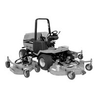
Textron Jacobsen HR-5111 Technical/Repair Manual (423 pages)
Brand:
Textron
| Category:
Lawn Mower
| Size: 46.93 MB
Table of Contents
Chapter 1 Safety 1
9
Table of Contents
9
Introduction
10
Prepare for the Job
10
Safety Label Locations
10
Safety Notices
10
Inspect Safety Labels
14
Keep Work Area Clean
14
Keep Work Area Well Ventilated
14
Park Mower Safely
14
Use Proper Eye and Face Protection
14
Support Machine Securely
15
Use Compressed Air and Air Tools Safely
15
Use Lifting Equipment Safely
15
Handle Fuel Safely
16
Service Tires Safely
16
Store Volatile and Hazardous Materials Safely
16
Handle Chemical Products Safely
17
Service Cooling System Safely
17
Service Hydraulic System Safely
17
Dispose of Waste Materials Safely
18
Service Electrical Components Safely
18
Chapter 2 Specifications and General Information
19
Mower Identification
20
Serial Number
20
Component Location
21
Engine Serial Number
21
Optional Machine Accessories
21
Specifications
23
Quick Reference Specifications
23
Chapter 3 Engine
31
General Engine Specifications
32
Repair Specifications
32
Specifications
32
Component Location
33
Kubota V2203-DI-B
33
Checks and Adjustments
35
Throttle Cable
35
Fuel Solenoid Rod
36
Purging the Fuel System
36
Repair
37
Fan Belt
37
Air Cleaner Assembly
38
Muffler
39
Exhaust Manifold
40
Radiator/Hydraulic Oil Cooler
41
Thermostat
44
Throttle Cable and Control Lever
44
Fuel Filter
45
Fuel Pump
46
Engine
47
Engine Service
50
Chapter 4 Electrical
51
Specifications
54
Theory and Diagnostic Information
55
Electrical Component Symbols
55
Electrical Schematic Component Identification
58
Electrical Schematic
60
Theory of Operation and Sub-Circuit Schematics
68
Power Circuit-Theory of Operation
68
Power Circuit Schematic
69
Glow Plug Circuit-Theory of Operation
76
Glow Plug Circuit Schematic
77
Start Circuit-Theory of Operation
78
Start Circuit Schematic
79
Run Circuit-Theory of Operation
80
Run Circuit Schematic-On Seat
81
Run Circuit Schematic-Off Seat
82
Charging Circuit-Theory of Operation
84
Charging Circuit Schematic
85
Mow Circuit-Theory of Operation
86
Mow Circuit Schematic
87
Four Wheel Drive Circuit-Theory of Operation
90
Four Wheel Drive Circuit Schematic
91
Four Wheel Drive Reverse Circuit Schematic
92
Cruise Control-Theory of Operation
94
Cruise Control Circuit Schematic
95
Cruise Control Disable Circuit Schematic
97
Work Lights Circuit-Theory of Operation
100
Work Lights Circuit Schematic
101
Instrumentation Circuit-Theory of Operation
103
Instrumentation Circuit Schematic
105
Horn/Test Circuit-Theory of Operation
108
Horn/Test Circuit Schematic
109
Troubleshooting
112
Glow Plug Circuit
112
Start Circuit
112
Run Circuit
113
Charging Circuit
113
Mow Circuit
113
Four Wheel Drive Circuit
115
Cruise Control Circuit
116
Work Light Circuit
116
Instrumentation Circuit
117
Horn and Audible Alert Circuit
121
Component Testing
122
Electrical System and Component Testing
122
Circuit Breakers Test
123
Thermal Circuit Breakers Test
123
Relays Test
124
Time Delay Relay Test
124
Key Switch Test
125
Horn/Test Switch Test
125
Seat Switch Test
126
Glow Plug Switch Test
126
Front Limit Switch Test
127
PTO Switch Test
127
Front Mow Enable Switch Test
128
Wing Mow Enable and Light Switches Test
129
Cruise Control Switch Test
130
4WD Switch Test
131
Micro Switches Test
132
Diff Lock Switch Test
132
Fuel Level Sensor Test
133
Solenoids Test
133
Fuel Shutoff Solenoid Test
134
Diodes Test
135
Fuel Pump Test
135
Repair
136
Battery and Battery Tray
136
Alternator
136
Starter Motor
137
Circuit Breakers
137
Thermal Circuit Breakers
138
Relays
138
Time Delay Relay
139
Key Switch
140
Park Brake Switch
141
Brake Pedal Switch
141
Horn/Test Switch
142
Seat Switch
142
Glow Plug Switch
143
Engine Temperature Gauge
144
Indicator Lights
145
PTO Switch
146
Right and Left Wing Proximity Switches
147
Front Limit Switch
147
Rocker Switches
148
Reverse Kick-Out Switch
149
Diff Lock Switch
150
Air Filter Pressure Switch
150
Return Filter Pressure Switch
151
Hyd Oil Temp Switch
151
Charge Filter Pressure Switch
152
Engine Oil Pressure Switch
153
Engine Temperature Sensor
153
Engine Coolant Temp Switch
154
Low Charge Pressure Switch
154
Mow Solenoids
155
4WD Solenoids
156
Glow Plug Solenoid
157
Fuel Shutoff Solenoid
158
Cruise Control Magnet
158
Diodes
159
Instrument Panel
160
Engine Speed Sensor
160
Volt Meter, Hour Meter, and Fuel Gauge
161
Tachometer
162
Horn
162
Fuel Level Sensor
163
Chapter 5 Hydrostatic Power Train
165
Repair Specifications
167
Specifications
167
Test and Adjustment Specifications
167
Portable In-Line Filter
168
Component Location
169
Theory of Operation and Sub-Circuit Schematics
171
Traction Circuit Neutral Schematic and Theory of Operation
171
Traction Circuit-Neutral Schematic
171
Traction Circuit-Forward 2WD Schematic and Theory of Operation
175
Traction Circuit-Forward 2WD, Differential Locked Schematic
176
Traction Circuit-Reverse 2WD Schematic and Theory of Operation
179
Traction Circuit-Reverse 2WD, Differential Unlocked Schematic
180
Traction Circuit-Forward 4WD Schematic and Theory of Operation
183
Traction Circuit-Forward 4WD, Differential Locked Schematic
184
Traction Circuit-Reverse 4WD Schematic and Theory of Operation
187
Traction Circuit-Reverse 4WD, Differential Unlocked Schematic
188
Troubleshooting
190
Tests and Adjustments
193
Traction Linkage Adjustments
193
Weight Transfer Adjustment
196
Field Test Procedures
197
Preliminary Checks
197
Charge Pump Test
197
Traction System Test
197
Instrument Test Procedures
198
Instrument Test Overview
198
Charge Pressure Test
198
Charge Pump Test
199
Traction System Test
201
Traction Pump Tests
204
Front Axle Motor Test
206
Front Axle U-Joint
211
Repair
211
Traction Pump U-Joint
212
Traction Pump
214
4WD Valve
217
Control Valve
219
Front Axle Motor
222
Front (Drive) Axle Assembly
224
Differential Lock Assembly
228
Input Bevel Pinion Assembly
229
Drive Axle Reducer Assembly
233
Differential Assembly
237
Rear Wheel Motor
241
Traction Linkage
245
Chapter 6 Hydraulics
247
Component Location
250
Hydraulic Schematic
252
Steering Circuit Schematic and Theory of Operation
258
Theory of Operation and Diagnostic Information
258
Steering Circuit Schematic
259
Raise Circuit Schematic and Theory of Operation
260
Raise Circuit Schematic
261
Lower Circuit Schematic and Theory of Operation
262
Lower Circuit Schematic
263
Mower Deck Float Circuit Schematic
264
Mower Deck Float Circuit Schematic and Theory of Operation
264
Mow Circuit (ON) Schematic and Theory of Operation
266
Mow Circuit (ON) Schematic
267
Mow Circuit (OFF) Theory of Operation
268
Mow Circuit (OFF) Schematic
269
Field Test Procedures
270
Front Lift Cylinders Leakage Test
270
Wing Lift Cylinders Leakage Test
271
Power Steering Circuit Test
272
Cutting Unit System Test
272
Instrument Test Procedure
273
Instrument Test Overview
273
Front Cutting Unit Circuit Test
274
Front Cutting Unit Pump Test
275
Front Cutting Unit Deck Valve Test
277
Adjust Front Cutting Unit Deck Valve System Relief Valve Pressure
279
Front Cutting Unit Motors Test
280
Right Wing Cutting Unit Circuit Test
283
Right Wing Cutting Unit Pump Test
285
Right Wing Cutting Unit Deck Valve Test
286
Adjust Right Wing Cutting Unit Deck Valve System Relief Valve Pressure
288
Right Wing Cutting Unit Motors Test
289
Left Wing Cutting Unit Circuit Test
292
Left Wing Cutting Unit Pump Test
293
Left Wing Cutting Unit Deck Valve Test
295
Adjust Left Wing Cutting Unit Deck Valve System Relief Valve Pressure
297
Left Wing Cutting Unit Motors Test
298
Lift/Steer System Relief Valve Pressure Test
300
Lift/Steer Pump Test
302
Repair
304
Hydraulic Oil Tank-Drain Procedure
304
Gear Pump
304
Deck Motors
307
Lift Valve
308
Right Deck Valve
310
Left Deck Valve
311
Front Deck Valve
312
Hydraulic Oil Return Filter
313
Charge Pressure Filter
314
Front Lift Cylinders
315
Wing Lift Cylinders
319
Hydraulic Oil Cooler
323
Hydraulic Oil Tank
323
Chapter 7 Steering
327
Specifications
328
Component Location
329
Steering Linkage Adjustments
330
Tests and Adjustments
330
Steering Relief Valve Pressure Test
332
Steering Leakage Test
333
Repair
334
Steering Wheel
334
Steering Valve
334
Steering Console
344
Steering Cylinder
347
Tie Rod Assembly
350
Rear Axle
352
Chapter 8 Cutting Units
357
Specifications
358
Component Location
359
Tests and Adjustments
360
Deck Leveling Adjustment
360
Deck Rake Adjustment
360
Final Adjustments
362
Troubleshooting
363
Mechanical Troubleshooting
363
Quality of Cut Troubleshooting
364
Repair
372
Deck Motor
372
Blade
374
Front Deck
375
Front Lift Arms
377
Wing Decks
379
Wing Deck Lift Arms
381
Swivel Caster Wheels
383
Fixed Caster Wheels
384
Anti-Scalp Wheels
385
Chapter 9 Accessories and Miscellaneous Repair
387
Component Location
389
Brake Pedal Adjustment
390
Checks and Adjustments
390
Park Brake Adjustment
390
Bleed Brake System
391
Repair
391
Canopy
391
Ops
392
Hood
392
Fuel Tank
393
Seat and Seat Platform
399
Floorboard
402
Work Light Kit
403
Rear Wheels
403
Front Wheels
404
Brake Pedal
405
Brake Master Cylinder
406
Brake Caliper
406
Advertisement
Advertisement
Related Products
Textron RANSOMES JACOBSEN HR6010
Textron Jacobsen HR 9016 Turbo
Textron Jacobsen HR800
Textron Jacobsen Greens King VI 62376
Textron Jacobsen Greens King VI 62375
Textron Jacobsen Greens King VI 62377
Textron Jacobsen Greens King VI 62378
Textron JACOBSEN G-PLEX III DN
Textron JACOBSEN G-PLEX III DP
Textron JACOBSEN G-PLEX III Series
Textron Categories
Crimp tool
Lawn Mower
Power Tool
Cutter
Measuring Instruments
More Textron Manuals
Login
Sign In
OR
Sign in with Facebook
Sign in with Google
Upload manual
Upload from disk
Upload from URL