Sign In
Upload
Manuals
Brands
TEXIO Manuals
Power Supply
PAR-A Series
TEXIO PAR-A Series Manuals
Manuals and User Guides for TEXIO PAR-A Series. We have
1
TEXIO PAR-A Series manual available for free PDF download: Instruction Manual
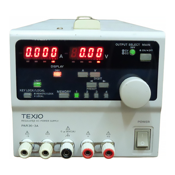
TEXIO PAR-A Series Instruction Manual (60 pages)
Brand:
TEXIO
| Category:
Power Supply
| Size: 1 MB
Table of Contents
Table of Contents
2
Using the Product Safely
9
About this Manual
9
Outline of Product
9
Features
9
PAR-A Power Supply Unit
9
IF-41Rs(Option
10
IF-41Gu(Option
10
IF-41Usb(Option
10
Accessories
10
2 Specifications
11
3 Instructions on Use
14
Checking Source Voltage
14
Connecting AC Cable
14
Precautions for Connecting Output Terminals
14
Installation Environments
14
4 Panels
15
Front Panel
15
Rear Panel
19
Bottom Plate
20
5 General Instructions
21
Turning on Power
21
Display When Power Is Turned on
21
Initial Setting When Power Is Turned on
22
Overheat Alarm (OHA)
22
Changing Source Voltage
23
Connecting Loads
24
6 Functions and Operation Procedures
25
Basic Operations
25
Set Value and Output Value Display
25
Voltage Setting Procedures
25
Current Setting Procedures
25
Fine Adjustment of Voltage (or Current)
25
Output Functions
26
Method of Turning on or off the Output with the MAIN OUTPUT Key
26
Method of Turning on or off the Output with the OUTPUT SELECT Key
26
Memory Function
26
Storing Preset Voltage/Current Values
27
Recalling Preset Values
27
Storing Values in Preset Memory in MAIN OUTPUT Key on Mode
27
Copying Preset Values
27
Storing Setting of each Key
28
Initializing Setting
28
Usage of KEYLOCK/LOCAL Key
28
Usage of Remote Sensing Function
29
Remote Sensing Terminals
29
Remote Sensing Connection
29
7 External Contact Control
30
Outline of Functions
30
Specifications of External Contact Control Connector
30
Operation Procedures
30
Turning On/Off MAIN OUTPUT Key through External Contacts
31
Selecting PRESET 1 Key to PRESET 4 Key through External Contacts
31
Detecting OHA Signal
31
Inputting Alarm Signal through External Contacts
31
Inputting Several Alarms through External Contaxts
31
8 Remote Control
32
Connecting IF-41RS
32
Remote Control Using Computer
33
Master Operation
34
Remote Control Using RT-63
35
Remote Control Using GP-620
36
Connecting IF-41GU/IF-41USB
36
Remote Control through GP-IB (IF-41GU Only)
37
Control through USB
37
Connecting IF-41GU/IF-41USB Local Bus
38
Setting Addresses
38
Addresses
38
Setting Addresses
39
Address Setting Range and Set Value
39
Transmission and Reception Procedures Using IF-41RS (Without Using GP-620)
40
Message Structure
41
Precautions for Sending or Receiving Message
43
Specifying Slave Machine as Talker from Master Unit
44
Acknowledge or Negative Acknowledge to Slave Units
44
Message Structure List When Using IF-41RS
44
Usage of IF-41GU/IF-41USB
46
Usage of GPIB (IF-41GU Only)
46
Usage of USB
46
Status Bytes
47
Application Configuration
47
Sending Commands (through GP-IB or USB)
48
Precautions for Sending Commands
48
Selecting Unit to be Controlled
48
Details of Commands
49
Setting Unit to be Controlled
49
Setting Voltage or Current
49
Turning On/Off MAIN OUTPUT Key
50
Turning On/Off OUTPUT SELECT Key
50
Selecting Preset Memory
50
Status Output Request
50
ID Output Request
51
Local Setting
51
Local Lockout
51
Disabling or Enabling Service Request
51
Storing Set Data
52
Checking Controlled Unit
52
Checking Connected Slave Unit
52
Inquiry about Optional Board ID
52
Sending Output Voltage, Output Current or Operation Mode (Response to the ST0 Command)
53
Sending All Preset Values (Response to the ST1 Command)
54
Sending All Equipment Statuses (Response to the ST2 Command)
54
Sending ID Data (Response to the ST3 Command)
54
Sending Output Voltage, Output Current or Operation Mode (Response to the ST4 Command)
54
Sending All Preset Values (Response to the ST5 Command)
54
Sending Power Supply Data (Response to the PWID Command)
55
Sending Address of Controlled Unit (IF-41GU/IF-41USB Only)
55
Sending Addresses of All Connected Slave Units (IF-41GU/IF-41USB Only)
55
Sending Optional Board ID (IF-41GU/IF-41USB Only)
55
Information of Constant-Voltage/Constant-Current Mode
55
Information of Alarm Status
56
Information about Completion of Storing the Set Data
56
Command List
57
9 Operation Failures
58
10 Outside Demensions
59
Advertisement
Advertisement
Related Products
TEXIO PAR18-6A
TEXIO PAR36-3A
TEXIO PA18-2B
TEXIO PA18-1.2B
TEXIO PA36-2B
TEXIO PA36-3B
TEXIO PA80-1B
TEXIO PA120-0.6B
TEXIO PA160-0.4B
TEXIO PA250-0.25B
TEXIO Categories
Power Supply
Test Equipment
Portable Generator
Recording Equipment
Multimeter
More TEXIO Manuals
Login
Sign In
OR
Sign in with Facebook
Sign in with Google
Upload manual
Upload from disk
Upload from URL