Sign In
Upload
Manuals
Brands
Texas Instruments Manuals
Motherboard
TPS56121
Texas Instruments TPS56121 Manuals
Manuals and User Guides for Texas Instruments TPS56121. We have
1
Texas Instruments TPS56121 manual available for free PDF download: User Manual
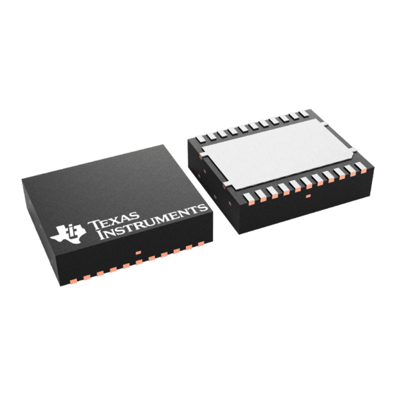
Texas Instruments TPS56121 User Manual (28 pages)
Step-Down Converter Evaluation Module
Brand:
Texas Instruments
| Category:
Motherboard
| Size: 1 MB
Table of Contents
Table of Contents
1
Introduction
3
Description
4
Applications
4
Features
4
Electrical Performance Specifications
5
Table 3-1. TPS56121EVM-601 Electrical Performance
5
Schematic
6
Figure 4-1. TPS56121EVM-601 Schematic
6
Test Setup
7
Test Equipment
7
Recommended Wire Gauge
7
Equipment Set up Procedure
8
Figure 5-1. TPS56121EVM-601 Recommended Test Setup
8
Configurations
9
Enable Selection (J3)
9
Test Point Descriptions
10
Input Voltage Monitoring (TP1 and TP2)
10
Output Voltage Monitoring (TP3 and TP4)
10
Enable/Soft-Start Monitoring (TP5)
10
Power Good Monitoring (TP6)
10
Loop Response Testing (TP7, TP8, TP9 and TP10)
10
Switch Node Voltage Monitoring (TP11 and TP12)
10
Table 7-1. Test Point Descriptions
10
Test Procedures
11
Start Up/Shut down Procedure
11
Output Ripple Voltage Measurement Procedure
11
Figure 8-1. Tip and Barrel Output Voltage Ripple Measurement
11
Control Loop Gain and Phase Measurement Procedure
12
Equipment Shutdown
12
Figure 8-2. Control Loop Measurement Setup
12
Performance Data and Typical Characteristic Curves
13
Efficiency
13
Load Regulation
13
Figure 9-1. Efficiency
13
Figure 9-2. Load Regulation
13
Line Regulation
14
Output Voltage Ripple
14
Figure 9-3. Line Regulation (VIN = 8 V to 14 V, VOUT = 1.0 V, IOUT = 15 A)
14
Figure 9-4. Output Voltage Ripple
14
Switch Node
15
Load Transient
15
Figure 9-5. Switch Node Waveform Measured at Pins Using Tip and Barrel Measurement Technique
15
Figure 9-6. Load Transient (VIN = 12 V, VOUT = 1.0 V, IOUT = 0 a to 15 A)
15
Vout = 1.0 V, Iout
15
Start up
16
Figure 9-7. Start-Up Waveform (VIN = 12 V, VOUT = 1.0 V, IOUT = 15 A)
16
Figure 9-8. Pre-Biased Start-Up Waveform (VIN = 12 V, VOUT = 1.0 V, IOUT = 0 A)
16
Power off
17
Over-Current Protection
17
Figure 9-9. Power-Off Waveform (VIN = 12 V, VOUT = 1.0 V, IOUT = 15 A)
17
Control Loop Bode Plot
18
Thermal Image
18
Figure 9-11. Loop Gain (VIN = 12 V, VOUT = 1.0 V, IOUT = 15 A, Bandwidth: 39 Khz, Phase Margin: 46°)
18
Figure 9-12. Thermal Image
18
EVM Assembly Drawings and PCB Layout
19
Figure 10-1. TPS56121EVM-601 Top Assembly Drawing (Top View)
19
Figure 10-2. TPS56121EVM-601 Bottom Assembly Drawing
19
Figure 10-3. TPS56121EVM-601 Top Copper (Top View)
20
Figure 10-4. TPS56121EVM-601 Internal
20
Figure 10-5. TPS56121EVM-601 Internal
21
Figure 10-6. TPS56121EVM-601 Bottom Copper
21
List of Materials
22
Revision History
22
Table 11-1. TPS56121EVM-601 List of Materials
22
Advertisement
Advertisement
Related Products
Texas Instruments SWIFT TPS561201EVM-896 1-A
Texas Instruments TPS560200
Texas Instruments TPS560200EVM-537
Texas Instruments TPS563231EVM-032
Texas Instruments TPS56C20
Texas Instruments TPS56C20EVM-614
Texas Instruments TPS562207EVM 2-A
Texas Instruments TPS563211
Texas Instruments TPS563211EVM
Texas Instruments TPS566235EVM-036
Texas Instruments Categories
Motherboard
Control Unit
Microcontrollers
Computer Hardware
Calculator
More Texas Instruments Manuals
Login
Sign In
OR
Sign in with Facebook
Sign in with Google
Upload manual
Upload from disk
Upload from URL