Sign In
Upload
Manuals
Brands
Texas Instruments Manuals
Motherboard
TPS53126EVM-600
Texas Instruments TPS53126EVM-600 Manuals
Manuals and User Guides for Texas Instruments TPS53126EVM-600. We have
1
Texas Instruments TPS53126EVM-600 manual available for free PDF download: User Manual
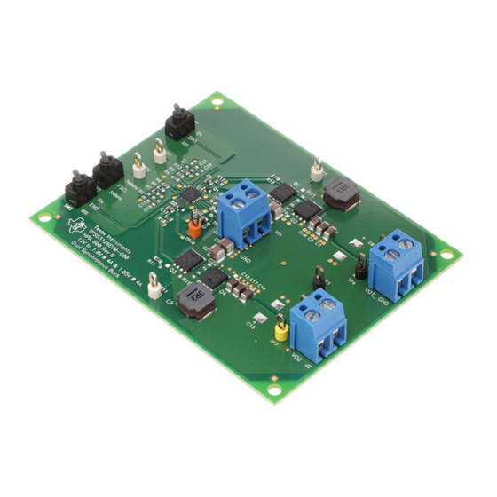
Texas Instruments TPS53126EVM-600 User Manual (25 pages)
TPS53126 Buck Controller Evaluation Module
Brand:
Texas Instruments
| Category:
Motherboard
| Size: 1 MB
Table of Contents
Table of Contents
1
TPS53126 Buck Controller Evaluation Module User's Guide
1
Introduction
3
Description
3
Applications
3
Features
3
Electrical Performance Specifications
4
Table 2-1. TPS53126EVM-600 Electrical and Performance Specifications
4
Schematic
5
Figure 3-1. TPS53126EVM-600 Schematic
5
Connector and Test Point Descriptions
6
Enable Switches - SW1 and SW2
6
Switching Frequency Select Switch - SW3
6
Test Point Descriptions
6
Table 4-1. TPS53126EVM-600 Test Points Description
6
Figure 4-1. Tip and Barrel Measurement for Output Voltage
7
Test Setup
8
Equipment
8
Recommended Setup
8
Figure 5-1. TPS53126EVM-600 Recommended Test Setup
9
Test Procedure
10
Start-Up Procedure
10
Line/Load Regulation and Efficiency Measurement Procedure
10
Output Ripple Voltage Measurement Procedure
10
Shutdown Procedure
10
Performance Data and Typical Characteristic Curves
11
Efficiency
11
Figure 7-1. Efficiency Vs Load
11
Figure 7-2. Efficiency Vs Load
11
Out1 = 1.05 V, Iout1 = 0 A-4 A)
11
Out2 = 0 A-4 A)
11
Line and Load Regulation
12
Figure 7-3. Output Voltage Vs Load
12
Figure 7-4. Output Voltage Vs Load
12
Out1 = 1.05 V, Iout1 = 0 A-4 A)
12
Output Voltage Ripple
13
Figure 7-5. Output Voltage Ripple
13
Figure 7-6. Output Voltage Ripple
13
OUT1 = 1.05 V, IOUT1 = 4 A, FSW = 350 Khz)
13
Switch Node Waveforms
14
Figure 7-7. Switching Waveform (VIN = 12 V, VOUT1 = 1.05 V, IOUT1 = 4 A, FSW = 350 Khz)
14
Figure 7-8. Switching Waveform (VIN = 12 V, VOUT2 = 1.08 V, IOUT2 = 4 A, FSW = 350 Khz)
14
EVM Assembly Drawings and Layout
15
Figure 8-1. Top Assembly
15
Figure 8-2. Bottom Assembly
15
Figure 8-3. Top Layer
16
Figure 8-4. Bottom Layer
16
Figure 8-5. Internal Layer 1
17
Figure 8-6. Internal Layer 2
17
Bill of Materials
18
Table 9-1. TPS53126EVM-600 Bill of Materials
18
Revision History
19
Advertisement
Advertisement
Related Products
Texas Instruments TPS53127EVM-614
Texas Instruments TPS53124
Texas Instruments TPS53129EVM-621
Texas Instruments TPS53126
Texas Instruments TPS53355EVM-864
Texas Instruments TPS53915
Texas Instruments TPS53317AEVM-726
Texas Instruments TPS53915EVM-PWR587
Texas Instruments TPS53015EVM-126
Texas Instruments TPS53819AEVM-123
Texas Instruments Categories
Motherboard
Control Unit
Microcontrollers
Computer Hardware
Calculator
More Texas Instruments Manuals
Login
Sign In
OR
Sign in with Facebook
Sign in with Google
Upload manual
Upload from disk
Upload from URL