Sign In
Upload
Manuals
Brands
Texas Instruments Manuals
Control Unit
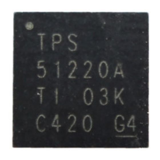
TPS51220A EVM-476
Texas Instruments TPS51220A EVM-476 Manuals
Manuals and User Guides for Texas Instruments TPS51220A EVM-476. We have
1
Texas Instruments TPS51220A EVM-476 manual available for free PDF download: User Manual
Texas Instruments TPS51220A EVM-476 User Manual (27 pages)
Buck Controller Evaluation Module
Brand:
Texas Instruments
| Category:
Control Unit
| Size: 1 MB
Table of Contents
Table of Contents
1
TPS51220A Buck Controller Evaluation Module User's Guide
1
Introduction
3
Description
3
Typical Applications
3
Features
3
Electrical Performance Specifications
3
Table 3-1. TPS51220A EVM-476 Electrical Performance Specifications
3
Schematic
5
Figure 4-1. TPS51220A EVM-476 Schematic
5
Test Setup
6
Test Equipment
6
Recommended Test Setup
6
Figure 5-1. TPS51220A EVM-476 Recommended Test
6
Figure 5-2. Recommended Tip and Barrel Technique to Measure Output Ripple Voltage
6
List of Test Points
7
Table 5-1. Test Point Functions Found on the TPS51220A EVM-476
7
Test Procedure
8
Line/Load Regulation and Efficiency Measurement Procedure
8
Output Ripple Test
9
Measuring Improved Light Load Efficiency
9
Table 6-1. SKIPSEL1 or SKIPSEL2 (Jumpers JP1 and JP4)
9
Control Architecture and OVP Select
10
Overcurrent Trip Level and Output Discharge Select
10
Table 6-2. FUNC (Jumper JP2) Selections
10
Table 6-3. TRIP (JP3) Selections
10
Performance Data and Typical Characteristic Curves
11
Efficiency
11
Load Regulation
11
Figure 7-1. Efficiency, 12 VIN , 5.0-V Output
11
Figure 7-2. Efficiency, 12 VIN , 3.3-V Output
11
Figure 7-3. 12 VIN , 5.0-V Load Regulation
11
Figure 7-4. 12 VIN , 3.3-V Load Regulation
11
Bode Plot
12
Transient Response
12
Figure 7-5. CCM Mode 5-V Loop Response Gain and Phase, F
12
Figure 7-6. CCM Mode 3.3-V Loop Response Gain and Phase, F
12
Figure 7-7. 5-V CCM Mode Load Transient
12
Figure 7-8. 5-V D-CAP Mode Load Transient
12
Output Ripple and Switch Node
13
Turn-On Waveform
13
Figure 7-9. 5-V CCM Mode Output Ripple and Switch Node
13
Figure 7-10. 3.3-V CCM Mode Output Ripple
13
Figure 7-11. Enable Turn-On Waveform
13
Turn-Off Waveform
14
Figure 7-12. Enable Turn-Off with Discharge Waveform
14
Figure 7-13. Enable Turn-Off Without Discharge Waveform
14
EVM Assembly Drawing and PCB Layout
15
Figure 8-1. Top Layer Assembly Drawing (Top View)
15
Figure 8-2. Bottom Assembly Drawing (Top View)
16
Figure 8-3. Top Copper (Top View)
17
Figure 8-4. Internal Layer 1 (Top View)
18
Figure 8-5. Internal Layer 2 (Top View)
19
Figure 8-6. Bottom Copper (Top View)
20
List of Materials
21
Revision History
21
Table 9-1. EVM Components List According to Schematic Shown in Figure 4-1
21
Advertisement
Advertisement
Related Products
Texas Instruments TPS55160Q1-EVM
Texas Instruments TPS55165Q1-EVM
Texas Instruments TPS53119EVM-690
Texas Instruments TPS54362B EVM
Texas Instruments TPS54672EVM-222
Texas Instruments TPS5430
Texas Instruments TPS5431
Texas Instruments TPS54226EVM-539
Texas Instruments TPS54521EVM-607
Texas Instruments TPS53313EVM-078
Texas Instruments Categories
Motherboard
Control Unit
Microcontrollers
Computer Hardware
Calculator
More Texas Instruments Manuals
Login
Sign In
OR
Sign in with Facebook
Sign in with Google
Upload manual
Upload from disk
Upload from URL