Sign In
Upload
Manuals
Brands
Texas Instruments Manuals
Motherboard
DS160PT801X16EVM
Texas Instruments DS160PT801X16EVM Manuals
Manuals and User Guides for Texas Instruments DS160PT801X16EVM. We have
1
Texas Instruments DS160PT801X16EVM manual available for free PDF download: User Manual
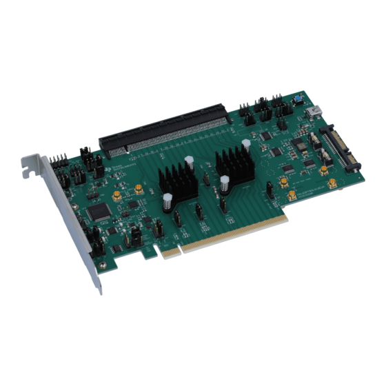
Texas Instruments DS160PT801X16EVM User Manual (45 pages)
Riser Card Evaluation Module
Brand:
Texas Instruments
| Category:
Motherboard
| Size: 3 MB
Table of Contents
Table of Contents
1
Figure 1-1. DS160PT801 EVM
1
EVM Control and Configuration Information
3
Retimer Pin Controls
3
Figure 1-1. DS160PT801X16EVM EEPROM Control and Connection
3
USB-To-Smbus Interface
4
Table 1-1. Default EVM Jumper Positions
4
Pcie PRSNT# Signal Control and Configuration
5
Pcie Reference Clock Control and Configuration
5
Figure 1-2. DS160PT801X16EVM Smbus Interface Connections
5
Figure 1-3. DS160PT801X16EVM Pcie PRSNT# Controls
5
Figure 1-4. Common Clock Topology Example
6
Figure 1-5. Independent Clock Topology Example
6
EVM Power
7
Figure 2-1. 1.17-V Power Supply Pin Controls
7
Figure 2-2. DS160PT801X16EVM Power Network
7
EVM Current Sensing
8
Figure 2-3. DS160PT801X16EVM Current Sense Measurement Locations
8
Sigcon Architect GUI
9
Setup and Installation
9
Configuration Page
10
Figure 3-1. Configuration Page Screenshot
10
Low-Level Page
11
Figure 3-2. Low-Level Page Screenshot
11
EEPROM Page
12
Figure 3-3. EEPROM Page Screenshot
12
Control Panel
13
Figure 3-4. Control Panel Screenshot
13
High-Level Page
14
Figure 3-5. High-Level Page Screenshot
14
Figure 3-6. High-Level Page - Device Status Screenshot
15
Figure 3-7. High Level Page - Device Status (Active Link)
16
Figure 3-8. High-Level - Rx EQ/DFE Page
16
Figure 3-9. High-Level Page Tx FIR
17
Diagnostic Page
18
Figure 3-10. Diagnostic Page Screenshot
18
Eye Monitor Page
19
Figure 3-11. Eye Monitor Page Screenshot
19
PCB Material Information
20
DS160PT801 PCB Design
20
DS160PT801 PCB Stackup
20
DS160PT801 PCB Power Distribution
20
Figure 4-1. DS160PT801X16EVM PCB Stackup
20
Figure 4-2. Layer 3 High-Speed Analog Analog Power Rails
21
Figure 4-3. Layer 4 Digital Power Rails
21
DS160PT801 Local Decoupling
22
Figure 4-4. Layer 9 and 10 Power Distribution
22
Figure 4-5. Decoupling Solution Frequency Response
22
Figure 4-6. PCB Top Layer
23
DS160PT801X16EVM Schematic
24
Figure 5-1. Schematic - Cover Sheet
24
Figure 5-2. Schematic - High Speed
25
Figure 5-3. Schematic - Control
26
Figure 5-4. Schematic - Supply Voltage Regulators
27
Figure 5-5. Schematic - Retimer 1 Current Sense and Decoupling
28
Figure 5-6. Schematic - Retimer 0 Current Sense and Decoupling
29
Figure 5-7. Schematic - Pcie Gen4 Clock Generation
30
Figure 5-8. Schematic - Pcie Gen4 Clock Buffer
31
Figure 5-9. Schematic - MSP430 Microcontroller
32
Hardware BOM
33
Table 6-1. DS160PT801X16EVM Bill of Materials
33
Revision History
39
Advertisement
Advertisement
Related Products
Texas Instruments DS125BR800EVM
Texas Instruments DS125BR111EVM
Texas Instruments DS125DF1610
Texas Instruments DS160PR810EVM-RSC
Texas Instruments DS125BR820EVM
Texas Instruments DS100MB203EVK
Texas Instruments DS100BR410EVK-4
Texas Instruments DS110DF111EVM
Texas Instruments DS125DF111EVM
Texas Instruments DS100BR210EVK
Texas Instruments Categories
Motherboard
Control Unit
Microcontrollers
Computer Hardware
Calculator
More Texas Instruments Manuals
Login
Sign In
OR
Sign in with Facebook
Sign in with Google
Upload manual
Upload from disk
Upload from URL