Sign In
Upload
Manuals
Brands
Telit Wireless Solutions Manuals
Control Unit
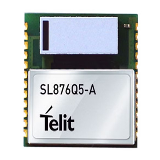
SL876Q5-A
Telit Wireless Solutions SL876Q5-A Manuals
Manuals and User Guides for Telit Wireless Solutions SL876Q5-A. We have
1
Telit Wireless Solutions SL876Q5-A manual available for free PDF download: Product User Manual
Telit Wireless Solutions SL876Q5-A Product User Manual (68 pages)
Brand:
Telit Wireless Solutions
| Category:
Control Unit
| Size: 3 MB
Table of Contents
Notice
2
Copyrights
2
Computer Software Copyrights
2
Usage and Disclosure Restrictions
3
Product Applicability Table
4
Table of Contents
5
1 Introduction
11
Purpose
11
Contact and Support Information
11
Text Conventions
12
Related Documents
13
Related Documents Requiring a Non-Disclosure Agreement
13
2 Product Description
14
Product Overview
14
SL876Q5-A Block Diagram
15
Figure 2-1 SL876Q5-A Block Diagram
15
SL876Q5-A Module
16
Figure 2-2 SL876Q5-A Module Photo
16
3 Sl876Q5-A Evaluation Kit (Evk)
17
Figure 3-1 Evaluation Kit (EVK) Contents
17
SL876Q5-A Evaluation Board (EVB)
18
Figure 3-2 SL876Q5-A Evaluation Board
18
4 Product Features
19
Built-In Antenna and Switch
19
Multi-Constellation Navigation
19
Quasi-Zenith Satellite System (QZSS) Support
19
Satellite Based Augmentation System (SBAS)
19
SBAS Corrections
19
SBAS Ranging
19
Assisted GPS (AGPS) - Sirfinstantfix
19
Client-Generated Extended Ephemeris (CGEE)
20
Server-Generated Extended Ephemeris (SGEE)
20
2-D Positioning
20
Static Navigation
20
Velocity Dead-Reckoning
21
Jamming Rejection - Continuous Wave (CW) Jamming Mitigation21
21
Elevation Mask Angle
21
Hz Navigation
21
10 Hz Navigation
22
1Pps
22
I/O Communication Ports
22
Power Management
23
Full Power Mode
23
Smartgnss
23
Table 4-1 Power Management Modes
23
Trickle Power
24
Push-To-Fix
24
Sirfaware
24
Hibernate
24
Internal LNA
25
Device Wake-Up (1 Port)
25
MEMS Wakeup (2Nd Port - I2C)
25
Host I/O Ports
25
5 Product Performance
26
Horizontal Position Accuracy
26
Time to First Fix
26
Table 5-1 SL876Q5-A Horizontal Position Accuracy
26
Table 5-2 SL876Q5-A Time to First Fix
26
Sensitivity
27
Table 5-3 SL876Q5-A Sensitivity
27
6 Software Interface
28
NMEA Output Messages
28
Standard Messages
28
Table 6-1 Default NMEA Output Messages
28
Table 6-2 Available NMEA Output Messages
28
Sirf Proprietary Messages
29
Telit Proprietary Messages
29
Table 6-3 NMEA Talker Ids
29
NMEA Input Commands
30
Change Output Sentences and Their Rates
30
Change Data Rate
30
Switch to OSP Protocol
30
OSP Output Messages
30
OSP Input Commands
30
Change Output Messages
30
Switch to NMEA Protocol and Data Rate
30
7 Flash Upgradability
31
8 Electrical Interface
32
Module Pin-Out
32
Figure 8-1 SL876Q5-A Pin-Out Diagram
32
Table 8-1 SL876Q5-A Pin-Out Function Table
34
DC Characteristics
35
Absolute Maximum Ratings
35
Table 8-2 DC Characteristics
35
Table 8-3 Absolute Maximum Ratings
35
Power Supply
36
Supply Voltage
36
Voltage Supply Capacitance
36
DC Power Requirements
36
Table 8-4 DC Supply Voltage
36
DC Power Consumption
37
Table 8-5 Power Consumption - SL876Q5-A
37
Table 8-6 Power Consumption - SL876Q5-A Low Power Modes
37
Control Input Signals
38
ON-OFF (Input) and SYSTEM-ON (Output)
38
Nreset
38
Boot Select
39
Internal / Nexternal Antenna Enable
39
Control Output Signals
39
1Pps
39
SYSTEM-ON (Output)
39
LNA Enable
39
RF Interface
40
Built-In Chip Antenna
40
External RF Input
40
8.7.3 Ground Plane
40
Table 8-9 Ground Plane Size
40
External Active Antenna Voltage
41
Burnout Protection
41
Jamming Rejection
41
Frequency Plan
41
Local Oscillator Leakage
41
Table 8-7 Frequency Plan
41
Table 8-8 lo Leakage
41
Host I/O Ports - Configuration and Operation
42
Primary Host Port Configuration
42
Secondary Host Port Configuration
42
UART Operation
42
Table 8-10 Primary Host I/O Port Configuration
42
I 2 C Operation
43
Table 8-11 UART Pin Assignments
43
SPI Operation
44
Table 8-12 I C Pin Assignments
44
Table 8-13 SPI Mode Pin Assignments
44
9 Reference Design
45
Figure 9-1 Reference Design
45
10 Rf Front End Design Considerations
47
RF Signal Requirements
47
GNSS Antenna Polarization
48
Active Versus Passive Antenna
48
GNSS Antenna Gain
49
System Noise Floor
49
PCB Stack and Trace Impedance
50
RF Trace Losses
50
Figure 10-1 RF Trace Examples
50
Implications of the Pre-Select SAW Filter
51
RF Interference
51
Shielding
51
Powering an External LNA (External Active Antenna)
52
Table 10-1 Inductor Loss
52
11 Mechanical Drawing
53
Figure 11-1 SL876Q5-A Mechanical Drawing
53
12 Pcb Footprint
54
Figure 12-1 SL876Q5-A Footprint and Ground Plane
54
Figure 12-2 SL876Q5-A PCB Footprint (Detail)
55
13 Product Packaging and Handling
56
Product Labelling and Serialization
56
Product Label - SL876Q5-A
56
Figure 13-1 SL876Q5-A Product Label
56
Table 13-1 SL876Q5-A Product Label Description
56
Product Packaging
57
Figure 13-2 Product Packaging - Tray 90 Pcs. each
57
Moisture Sensitivity
58
Figure 13-3 Moisture-Sensitive Device Label
58
ESD Sensitivity
59
Reflow
59
Assembly Considerations
59
Washing Considerations
59
Safety
59
Disposal
59
14 Environmental Requirements
60
Operating Environmental Limits
60
Storage Environmental Limits
60
Table 14-1 Operating Environmental Limits
60
Table 14-2 Storage Environmental Limits
60
15 Compliances
61
EU Declaration of Conformity
61
Rohs Certificate
61
16 Glossary and Acronyms
62
17 Safety Recommendations
65
Read Carefully
65
Electrical and Fire Safety
66
18 Document History
67
Advertisement
Advertisement
Related Products
Telit Wireless Solutions SL871
Telit Wireless Solutions SL871L
Telit Wireless Solutions SL871-S
Telit Wireless Solutions SL871L-S
Telit Wireless Solutions SL869T3-I
Telit Wireless Solutions SL869x-V2 Series
Telit Wireless Solutions SL869-V2
Telit Wireless Solutions SL869-V2S
Telit Wireless Solutions SL869L-V2
Telit Wireless Solutions SL869L-V2S
Telit Wireless Solutions Categories
Control Unit
Wireless modules
Motherboard
Computer Hardware
Microcontrollers
More Telit Wireless Solutions Manuals
Login
Sign In
OR
Sign in with Facebook
Sign in with Google
Upload manual
Upload from disk
Upload from URL