Sign In
Upload
Manuals
Brands
Teletype Manuals
Typewriter
14
Teletype 14 Typing Reperforator Manuals
Manuals and User Guides for Teletype 14 Typing Reperforator. We have
2
Teletype 14 Typing Reperforator manuals available for free PDF download: Bulletin, Manual
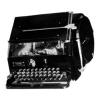
Teletype 14 Bulletin (50 pages)
Brand:
Teletype
| Category:
Typewriter
| Size: 3 MB
Table of Contents
Table of Contents
6
Spring Tensions
10
Receiving Range Adjustment
10
1.E. PULLING MAG NET SELECTOR
10
2. Adjust Me Nts
11
2.A. TYPING UNIT
11
2) Main Shaft Adjustment
11
5) Main Shaft Clutch Spring Tension
11
3) Main Shaft Clutch Throwout Lever Adjustment
11
4) Main Shaft Clutch Throwout Lever Spring Tension
11
6) Motor Position Adjustment
11
7) Pulling Magnet Selector Mechanism Adjustments
11
7) (A) Selector Armature Bracket Link Friction Adjustment
11
7) (C) Selector Armature Adjustment
12
7)(E) Selector Armature Bracket Adjustment
12
7)(D) Selector Armature Bracket Link Adjustment
12
7)(B) Selector Lever Spring Tension
12
7)(H) Armature Locking Lever Spring Tension
13
7)(G) Armature Locking Wedge Adjustment
13
7) (F) Armature Stops Adjustment
13
7)(I) Stop Lever Eccentric Screw Adjustment
13
7)(J) Stop Lever Spring Tension
13
7)(1) Trip Latch Spring Compression
13
8) Holding Magnet Selector Mechanism Adjustments
14
8)(A) Armature Pivot Screw Adjustment
14
8)(D) Selector Arm Bracket Adjustment
14
8)(C) Selector Arm Pivot Screw Adjustment
14
8)(B) Selector Magnet Adjustment
14
7)(M) Armature Trlp-Off Eccentric Screw Adjustment
14
7)(0) Magnet Bracket Adjustment
14
7) (N) Magnet Coil S Adj Ustment
14
2.A.(8)(F) LOCKING LEVER SPRING TENSION
15
2.A.(8)(E) LOCKING WEDGE ADJUSTMENT
15
2. A. (8)(G) Selector Arm Stop Detent Adjustment
15
8)(H) Selector Arm Stop Detent Spring Tension
15
8)(I) Selector Lever Spring Tension
15
8)(K) Selector Magnet Bracket Adjustment
15
8)(J) Selector Magnet Bracket Position Adjustment
15
8)(1) Armature Spring Tension Adjustment
16
8)(M) Selector Arm Operating Screw Adjustment
16
2.A.(8)(N) SELECTOR ARM SPRING TENSION
16
8)(R) Selector Stop Arm and Stop Lever Engagement Adjustment
16
8)(0) Stop Lever Eccentric Screw Adjustment
16
8)(Q) Stop Lever Spring Tension
16
8)(P) Trip Latch Spring Compression
16
8)(S) Trip-Off Screw Adjustment
17
14) Function Bar Bracket Plates Adjustment
18
16) Main Bai I Guide Post Adjustment
18
17) Pull Bar Guide Adjustment
18
15) Pull Bar Springs Tension
18
12) Ribbon Feed Lever Spring Tension
18
22) Carriage Bracket Locating Plate
19
23) Carriage Locking Pawl Post Adjustment
19
29) Carriage Return Spring Tension
19
41) Left Ribbon Reverse Arm Shaft Adjustment
19
24) Left Tape Guide Adjustment
19
18) Main Bail Adjusting Screw Adjustment
19
32) Carriage Extension Adjustment
20
30) Carriage Locking Pawl Spring Tension
20
35) Pull Bar Lock-Out Lever Adjustment
20
36) Ribbon Guide Adjustment
20
47) Ribbon Feed Shaft Safety Spring Compression
21
56) Bell Hammer Eccentric Screw Adjustment
22
54) Left Function Pull Bar Spring Bracket Adjustment
22
58) Mainbailcamclutchtorque
22
49) Ribbon Check Pawl Adjustment
22
SO) Ribbon Check Pawl Spring Pressure
22
51) Ribbon Feed Pawl Adjustment
22
52) Ribbon Feed Pawl Spring Pressure Adjustment
22
48) Ribbon Feed Shaft Detent Plunger Spring Compression
22
60) Bell and Break Contact Mechanism Adjustment
23
60) (A) Double Contact Mechanism
23
60)(A)2. Bell Hammer Adjustment
23
60)(A)5. Break Signal Contact Spring Adjustment
23
60)(A)3. Contact Mounting Screws Adjustment
23
60)(A)4. Contact Springs Adjustment
23
60)(A)1. Detent Arm Spring Tension
23
60)(B) Single Contact Mechanism
23
60)(B) 1. Contact Springs Adjustment for Single Contact Mechanism
23
61) Mechanical End-Of-Line Indicator Adjustment
23
61)(H) Cam Lever Spring Tension
24
61)(E) Worm Follower Spring Tension
24
63) Mechanical Motor Control Mechanism on Upper Case "H" Adjustments
24
63)(A) Contact Lever Bracket Adjustment
24
63)(D) Contact Lever Spring Tension
24
63)(B) Latch Lever Bracket Extension Adjustment
24
63)(C) Latch Lever Extension Adjustment
24
2.A.(63)(E) LATCH LEVER SPRING TENSION
24
62) Mechanism to Prevent Printing and Spacing on Lower Blank Adjustments
24
62) (B) Space Suppression Lever Adj Ustment
24
63)(H) Contact Lever Adjusting Screw Adjustment
25
63)(I) Main Bail Spring Adjustment
25
63)(G) Motor Control Contacts Adjustments
25
65) Positive Carriqge Shift Mechanism Adjustment
25
65)(C) Carriage Locking Toe Adjustment
25
65) (B) Figures Stop Screw Adjustment
25
65) (A) Locking Pawl Post
25
64) Push Tape Feed Mechanism Adjustment
25
64)(C) Tape Feed Roll Spring Tension
25
65)(D) Carriage Capstan Nuts Adjustment
26
65)(1) Figures Locking Pawl Spring Tension
26
65)(E) Shift Plate
26
65)(H) Shift Plate Eccentric (Units Equipped with '84584 Release Pull Bar)
26
65)(G) Shift Plate (Units Equipped with #84584 Release Pull Bar)
26
2) Tape Lever Adjusting Clamp Adjustment
27
8) Tape Lever Spring Tension
27
11) Transmitting Cam Cyl Inder Adj Ustment
27
14) Transmitting Contacts Gap Adjustment
27
3) Trip-Off Pawl Stop Plate Adjustment
27
1) Universal Bar Pilot Screws Adjustment
27
15) Transmitting Contacts Spring Pressure
28
21) Trip-Off Pawl Eccentric Adjustment
28
23) Trip-Off Pawl Spring Tension
28
24) Repeat on Space' Mechanism Adjustments
29
24)(D) Jack Spring Tension
29
24)(F) Key Lever Spring Adjustment
29
24)(A) Repeat Space Rod Adjustment
29
24)(B) Repeat Space Rod Bracket Adjustment
29
24)(C) Tape Guide Tube Adjustment
29
24)(E) Typing Unit Slip Connections Spring Tension Adjustment
29
Governor Adjustments
31
6) Governor Brush Position
31
3) Governor Brush Spring Requirement
31
4) Governor Shims Adjustment
31
7) Inner and Outer Disc Contact Spring Adjustment
31
5) Speed Adjustment Lever Stop Plate Adjustment
31
2) Speed Adjusting Wheel Friction Washer Spring Tension Adjustment
31
10) Governor Adjusting Bracket Adjustment
32
8) Governor Brush Spring Plate Bracket Adjustment
32
2.C.(9) GOVERNOR BRUSH SPRING PRESSURE
32
9)(A) Inner Disc Brush Spring
32
9)(B) Outer Disc Brush Spring
32
2.D. SYNCHRONOUS MOTORS
32
2.D.(1) STARTING SWITCH ADJUSTMENTS
32
Lubr Icatn
33
Typing Unlt
33
46) Bell and Break Contact Mechanism
34
47) Mechanical End-Of-Line Indicator Mechanism
34
H" Mechanism
34
50) Push Tape Feed
34
48) Suppression of Printing and Spacing on Lower Case of BLANK Mechanism
34
3.B. KEYBOARD
34
21) Motor Control on Upper Case II HII
35
Advertisement
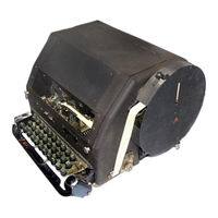
Teletype 14 Manual (41 pages)
Transmitter-Distributor
Brand:
Teletype
| Category:
Typewriter
| Size: 3 MB
Table of Contents
Table of Contents
1
General
2
Stop Magnet and Main-Shaft Clutch
2
Magnet Core
3
Main Shaft
3
Operating Lever Spring (on Units Equipped with All-Steel Clutch)
8
Single-Coil Universal Magnet
10
Start Magnet Bracket
12
Tape Feed Mechanism
16
Adjustable Tape Guide
18
Detent Bracket
19
Feed-Lever Adjusting Screw
21
Feed-Lever Stop
21
Operating Lever Adjusting Screw
21
Retaining Lid Latch
21
Tape Retaining Lid Plate
21
Feed-Lever Spring
22
Lower Contact Screws
24
Upper Contact Screws
25
Tape-Feed Withhold Mechanism
26
Armature Air Gap
26
Armature Spring
26
Blocking Plate Clearance
27
Feed-Pawl Clearance
27
Feed-Pawl Spring
27
Tight-Tape Stop Mechanism
27
Distributor Brushes (Carbon)
30
Operating Cam
33
Main-Shaft Clutch Torque {Friction Feed)
34
Tape-Out Mechanism {6Th Pin)
34
Torn-Feed-Hole Tape-Stop Assembly
35
End-Of-Tape Stop Contact Spring
35
Tape Retaining Lid Plate
35
Auxiliary Contacts {14W Only)
37
Slip Connection Contacts
37
0-Wpm Operation
38
Single-Step Tape-Feedsuppression Mechanism
40
Restoring Lever Eccentric
40
Restoring Lever Plate
40
Restoring Lever Spring
40
Tape Feed-Lever Latch
41
Tape Feed-Lever Latch Spring
41
Trip-Off Latch Spring
41
Advertisement
Related Products
Teletype 15
Teletype 1951
Teletype 1250
Teletype 1451
Teletype 15AND20
Teletype 35
Teletype 43 Basic KSR
Teletype 43 Basic KSR F W/TAU1
Teletype 43 Basic KSR F W/TAU2
Teletype 43 Basic KSR S W/TAU1
Teletype Categories
Printer
GPS
Typewriter
Keyboard
Security Sensors
More Teletype Manuals
Login
Sign In
OR
Sign in with Facebook
Sign in with Google
Upload manual
Upload from disk
Upload from URL