Sign In
Upload
Manuals
Brands
Telemark Cryogenics Manuals
Laboratory Equipment
19-0001-00
Telemark Cryogenics 19-0001-00 Manuals
Manuals and User Guides for Telemark Cryogenics 19-0001-00. We have
1
Telemark Cryogenics 19-0001-00 manual available for free PDF download: Instruction Manual
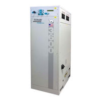
Telemark Cryogenics 19-0001-00 Instruction Manual (81 pages)
MICROPROCESSOR BASED WATER VAPOR
Brand:
Telemark Cryogenics
| Category:
Laboratory Equipment
| Size: 3 MB
Table of Contents
Table of Contents
2
1 Introduction
7
Safety Warnings
7
Warranty
11
User Responsibility
12
Intended Use of the Equipment
12
Standards
13
2 Specifications
14
Table 2-1, Model 1200, 1800, 1800EXT, 2400 Specifications
15
Table 2-2, Model 3000, 3600, 4800 Specifications
16
Environmental Conditions
17
Gas Cwp Chart
17
Table 2-3, Current Models Gas CWP Chart
17
Table 2-4, Discontinued Models Gas CWP Chart
17
Table 2-5, Environmental Conditions
17
Recommended Breaker and Wire Size
18
Table 2-6, Recommended Breaker and Wire Size
18
Physical Dimensions
19
Table 2-7, Physical Dimensions
19
3 Installation
20
Unpacking and Inspection
22
Figure 3-1, Removing Unit from Transportation Pallet
22
System Pressure
23
Location
23
Panel Removal
23
Figure 3-2, Pressure Gauge
23
Water Connections
24
Figure 3-3, Service Panel
24
Figure 3-4, Water Flow Requirements
25
Refrigerant Line Connection
26
Figure 3-5, Position of Hand Valves
26
Figure 3-6, Refrigerant Line Connections
27
Figure 3-7, Access Valve
28
Figure 3-8, Refrigerant Manifold
28
Refrigerant Line Installation Notes
29
Figure 3-9, Refrigerant Line Insulation
31
Main Electrical Connections
32
Figure 3-10, Metal O-Ring Removal Tool
32
Figure 3-11, Main Isolator Wiring
33
Table 3-1, Cryochiller Recommended Circuit Breaker Value and Wire Size
33
Transformer Connections
33
Figure 3-12, Transformer Tapings
34
Remote Connections
35
Digital Remote Control
35
Figure 3-13, 37-Way Amphenol™ Connector, Front View
37
Table 3-2, Pin Connection for 37-Way Amphenol Connector
37
Analogue Output Voltage
38
Table 3-3, Volts Vs. Temp Analog Output
38
Ethernet Communication
39
Figure 3-14, Ethernet Cable (Crossed)
39
Ethernet (Laptop) Set up
40
Figure 3-15, Network Connection Window
40
Figure 3-16, Network Properties
40
Figure 3-17, TCP/IP
41
Figure 3-18, Set up for TCP/IP
41
Commands Available When Using Ethernet, RS232/485 Control
42
Table 3-4, Write Serial Commands
42
Table 3-5, Read Serial Commands
42
Figure 3-19, TCP/IP GUI
43
GUI Button/Screen Functions
43
Using TCPIP-Rs232/485/Ethernet GUI
43
Cal2309" Screen (User Configuration Screen)
45
Figure 3-20, Ethernet TCP/IP and RS232/485 Help Screens
45
Figure 3-21, "Cal2309" Screen Setup
46
Using the Tcpip-Rs232/485 Program
48
Figure 3-22, Change Com Port
49
Figure 3-23, Select Com Port
49
Figure 3-24, Com Connection Shown
50
Figure 3-25, Enter Rip
50
Figure 3-26 Display IP Address
51
Figure 3-27, Change Remote Host
51
Figure 3-28, Go to IP Properties
52
Figure 3-29, Check IP Addresses
52
Figure 3-30, Parameter Setup
53
Figure 3-31, Select IP Address for Changing
53
Figure 3-32, Enter New IP Address
54
Figure 3-33, Disconnect TCP/IP
55
Figure 3-34, Change Remote Host IP Address
55
Figure 3-35, Disconnect TCP/IP Again
56
Figure 3-36, Check First Three IP Numbers
57
Figure 3-37, Connect to Remote Host
57
4 Operation
58
Controls and Displays
58
LCD Display
58
Figure 4-1, Front Panel Push Buttons (Single Coil Unit Shown)
58
Figure 4-2, LCD Display, Wait
58
Figure 4-3, LCD Display, Pre-Cool
59
Figure 4-4, , LCD Display, Ready
59
Figure 4-5, LCD Display, Cool
59
Table 4-1, Display Mnemonics and Their Meaning
59
Scroll Push Button
60
Push Buttons
60
COOL Push Button(S)/Indicators(S)
60
STOP/RESET Push Button
60
Operation
61
Turn on the Main ISO Isolator
61
Turning the Unit on
61
Standby
61
Cool
61
Defrost
61
Defrost Recovery Period
61
Normal Operating Ranges
62
Table 4-2, Normal Operating Ranges
62
5 Trouble Shooting Guide
63
Trouble Shooting
63
Refrigeration Leaks
63
Alarm Codes/Messages
63
Safety Systems
64
Hardware Safety Systems
64
Figure 5-1, "OVER PRESSURE" Alarm Message
64
Figure 5-2, "E1" with Fault Shown as "DP HIGH
64
Table 5-1, Listing of Alarm Messages and Error Codes
64
Trouble Shooting Guide
65
Table 5-2, Troubleshooting Guide
68
The Use of "Top-Off" Gas Charges
69
Emerson (Copeland™) Compressor
69
Figure 5-3, Emerson Compressor Front Panel Fault Code Led's
70
Figure 5-4, Emerson Compressor Internal Electronic Parts
70
Compressor Diagnostics
71
Table 5-3, Emerson Leds
74
6 Decommissioning
75
7 Design of Cryo-Coils
77
Table 7-1, Coil Surfaces and Theoretical Pumping
78
8 Chinese Safety Data Sheet
80
Advertisement
Advertisement
Related Products
Telemark Cryogenics 1200
Telemark Cryogenics 1800
Telemark Cryogenics 1800EXT
Telemark Cryogenics 2400
Telemark Cryogenics 3000
Telemark Cryogenics 3600
Telemark Cryogenics CRYO-CHILLER
Telemark Cryogenics Categories
Laboratory Equipment
More Telemark Cryogenics Manuals
Login
Sign In
OR
Sign in with Facebook
Sign in with Google
Upload manual
Upload from disk
Upload from URL