Sign In
Upload
Manuals
Brands
Teledyne SP Devices Manuals
Measuring Instruments
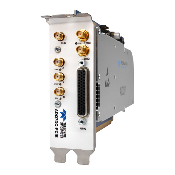
ADQ7DC
Teledyne SP Devices ADQ7DC Manuals
Manuals and User Guides for Teledyne SP Devices ADQ7DC. We have
1
Teledyne SP Devices ADQ7DC manual available for free PDF download: Manual
Teledyne SP Devices ADQ7DC Manual (50 pages)
Brand:
Teledyne SP Devices
| Category:
Measuring Instruments
| Size: 1 MB
Table of Contents
Table of Contents
2
1 Introduction
5
ADQ7DC Architecture
5
Fundamental Design Properties
5
Data Format
6
Calibration
6
Data Acquisition Nomenclature
6
ADQ7DC Sampling Clock Frequency
7
System Clocks
7
Analog Signal Range
7
2 Setting up the Analog Front-End
9
AFE Block Diagram
9
Set Analog DC-Offset
9
Adjusting the Digital Gain and Offset
10
3 Signal Quality Enhancement
11
Digital Baseline Stabilizer
11
Interleaving Correction ADX
11
4 Trigger
12
Trigger Block Diagram
12
Position of the Trigger in the Data
13
Timestamp
13
Timestamp Definitions
13
Timestamp Reset
14
Blocking Triggers for Synchronization
16
Function Overview
16
Block Triggers Once
17
Windowing Triggers
17
Gating and Windowing Triggers
17
Programming Sequence for Using Trigger Blocking
17
Trigger Jitter
18
Trigger Jitter Definitions
18
Asynchronous Triggering
18
Synchronous Trigger
19
Extended Trigger Resolution
19
Software Trigger
19
External Trigger Inputs
20
External Trigger TRIG Front Panel Connector
20
External Trigger SYNC Connector
21
Driving the External TRIG/SYNC Signal by Controlling Input Impedance
21
External Trigger in the Backplane
22
Pxie Interface
22
MTCA.4 Interface
23
Level Trigger
24
Setting the Level Trigger Level
25
Level Trigger and DBS
25
Controlling Noise Sensitivity
25
Internal Trigger
26
Trigger Output
26
1Trigger Output Port Selection
26
2Frame Sync Output on SYNC Connector
27
3Trigger Event Indicator
27
4Triggering External Equipment with Internal Trigger
27
5Distributing Level Trigger
29
5 Clock
30
Clock Domains
30
Flexible Clock Network
30
Front Panel SMA Connector
31
Internal Clock Reference
31
External Clock Reference
31
Internal Clock Generator
32
External Clock
32
Clock Reference Output
32
Sample Skip
32
6 Gpio
33
GPIO with TRIG and SYNC
33
Using GPIO as a Trigger
33
Output
34
GPIO in ADQ Development Kit
34
Dedicated GPIO Connector on Form Factor -Pcie or -Pxie
35
7 Acquisition Control
37
Multi-Thread Notice
37
Acquisition Memory
37
Acquisition Modes
38
Continuous Streaming Acquisition
38
Triggered Streaming Acquisition
39
Multi-Record Acquisition
39
Data Transfer Modes
40
Streaming Data Transfer Mode
40
User-Scheduled Data Transfer Mode
42
Transfer Buffers
44
User's Buffers
44
Users Application Software Consuming Data
44
Record Header
45
Metadata
45
Record Status
45
User ID
46
Serial Number
46
Channel
46
Record Number
46
Data Format
46
Record Length
46
Over-Range and Under-Range
47
8 Host Pc Connection
48
USB Interface
48
PCI Express Interface
48
Using Several Units
48
Using Several Digitizers from a Single Application
48
Using Several Digitizers from a Several Applications
48
9 References
49
Advertisement
Advertisement
Related Products
Teledyne SP Devices ADQ14-FWPD
Teledyne SP Devices ADQ14
Teledyne SP Devices ADQ7-FWATD
Teledyne SP Devices ADQ7
Teledyne SP Devices ADQ
Teledyne SP Devices ADQ8-8C
Teledyne SP Devices ADQ3 Series
Teledyne SP Devices ADQ32-PCIe
Teledyne SP Devices ADQ33-PCIe
Teledyne SP Devices ADQ36-PXIe
Teledyne SP Devices Categories
Measuring Instruments
Microcontrollers
More Teledyne SP Devices Manuals
Login
Sign In
OR
Sign in with Facebook
Sign in with Google
Upload manual
Upload from disk
Upload from URL