Sign In
Upload
Manuals
Brands
Teledyne Manuals
Recording Equipment
FPRC-1200
Teledyne FPRC-1200 Manuals
Manuals and User Guides for Teledyne FPRC-1200. We have
1
Teledyne FPRC-1200 manual available for free PDF download: Operation Manual
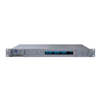
Teledyne FPRC-1200 Operation Manual (126 pages)
Redundant System Controllers
Brand:
Teledyne
| Category:
Recording Equipment
| Size: 3.61 MB
Table of Contents
Table of Contents
3
Section 1: General Information
9
Introduction
9
Description
9
Equipment Supplied
9
Figure 1-1: Outline Drawing, RCP2-1100 Redundant System Controller
10
Specifications
10
Outline Drawings
10
Safety Considerations
11
High Voltage Hazards
11
High Current Hazards
11
Electrical Discharge Hazards
12
Figure 2-1: RCP2/FPRC-1100/1200 Rear Panel
13
Inspection
13
Mounting
13
Storage and Shipment
13
Control Cable Connector (J3) - MS3112E16-23S
14
Figure 2-2: Rear Panel View of J3, MS3112E16-23S
14
Serial Port, Main (J4) - DB9 (F)
14
Table 2-1: J3 Switch Connector, MS3112E16-23S
14
Table 2-2: Main Serial Port Pin out
15
Table 2-3: Local Serial Port Pin out
15
Serial Port, Local (J5) - DB9 (M)
15
Program Port (J6) - DB25 (M)
15
Parallel I/O Connector (J7) - DB37 (F)
15
Table 2-4: Parallel I/O Signals
16
Table 2-5: External Alarm Port Pin out
17
External Alarm Port (J8) - DB9 (F) [IO Board Version 001]
17
Ethernet Port (J9) - RJ45 (F)
17
Table 2-6: Ethernet Port (J9) Pin Outs
17
Removable Power Supply Modules
18
V Power Supply Module
18
Figure 2-3: Removable Power Supply Module
18
Figure 2-3: Removable Power Supply Module, High Power Option
19
V Power Supply Module, High Power Option
19
V Power Supply Module
20
Figure 2-5: 48V Removable Power Supply Module
20
System Identification
21
Signal Path MIMIC Display
21
Figure 3-1: RCP2/FPRC Front Panel, Showing RCP2-1200 MIMIC Display
21
Figure 3-2: Fault Indicators
21
Amplifier Select Keys
22
Vacuum Fluorescent Display
22
Main Menu Key
22
Figure 3-3: Signal Path MIMIC Display
22
Local / Remote Key
23
Auto / Manual Key
23
Display Navigation Keys
23
Enter Key
23
Local / Remote Control
24
Methods of Switching
24
Manual Mode
24
Auto Mode
24
Physically Rotating Transfer Switch
24
Local (Front Panel) Menu Structure
25
Figure 3-4: Main Menu Initial Menu Selection
25
Sys Info
26
Figure 3-5: System Information Menu Structure
26
Sys Info - Page 1
27
Sys Info - Page 2
27
Sys Info - Page 3
28
Sys Info - Page 4
29
Sys Info - Page 5
29
Sys Info - Page 6
30
IP Info - Page 1
31
IP Info - Page 2
31
SSPA Subsystem Information - Pages 1-5
31
IP Info - Page 3
32
IP Info - Page 4
32
Baud Rate
33
Figure 3-6: Serial Communication Parameters Menu
33
Protocol
33
Serial Communication Parameters
33
Interface
34
IP Setup
34
Sys. Address
34
Operations Menu
34
Buzzer
34
Figure 3-7: Operation Parameters Menu
34
System
34
Control
35
Fault Setup
35
Figure 3-8: Fault Setup Parameters Menu
35
Priority
35
Stby. Select
35
Switching
35
Auxfaults
36
Fault Latch
36
Fault Logic
36
Mjrfaults
36
Rfsw.faults
36
Backup
37
Figure 3-9: Options Parameters Menu
37
Lamp Test
37
Options Menu
37
Password
37
Restore
37
Fault Tolerance
38
More
38
Reset
38
Sspa
38
Sys ID
38
VFD Light
38
Calibrate
39
Calibration Menu
39
Figure 3-10: Calibration Parameters Menu
39
Flt. Window
39
Lna/Lnb Ps
39
View LNA
40
Section 4: System Setup & Control with RCP
41
Operation of 1:2 System with RCP2-1200
45
LNA / LNB 1:2 Redundant System Operation
45
Figure 4-5: Block Diagram, 1:2 Redundant System
45
Figure 4-6: System Components, 1:2 Redundant LNA System
46
Figure 4-7: Schematic, Typical 1:2 Redundant LNA System
47
LNA / LNB Current Calibration
47
LNA/LNB Fault Tracking
47
External Alarm Tracking
48
Figure 4-8: Block Diagram, 1:2 SSPA Redundant System
48
SSPA 1:2 Redundant System Operation
48
Figure 4-9: Block Diagram, 1:1 Fixed Phase Combined System
49
Operation of 1:1 Fixed Phase Combined System with FPRC-1100
49
Figure 4-10: Block Diagram, 1:2 Fixed Phase Combined System
50
Operation of 1:2 Fixed Phase Combined System with FPRC-1200
50
RCP Remote Control of System Sspas
51
Configuring the RCP for Remote Control Mode
52
Table 4-1: Compact Outdoor SSPA Wiring
52
Table 4-2: Rack Mount SSPA Wiring
53
Table 4-3: Vbuc Wiring
53
Using M&C Features of RCP to Control a SSPA System
54
Change Mute State
54
Change Attenuation Level
55
Change Switch Mute Option Value
55
Units
55
View SSPA System Info
56
Advanced System Level Troubleshooting with RCP
58
Scenario 1
58
Scenario 2
58
Redundant Power Supplies
59
Digital Core Board
60
Figure 5-1: Block Diagram, Power Supply Configuration
60
I/O Board Assembly
61
Vacuum Fluorescent Display
61
Figure 5-2: Block Diagram, RCP Digital Core Board
61
Front Panel MIMIC Display
62
Control Cable Considerations
62
Table 5-1: Commonly Used Waveguide Transfer Switches
62
Figure 5-3: Cable Losses to Transfer Switch
63
Table 5-2: Maximum Cable Length for Selected Switches (Single Switch Systems)
63
Figure 6-1: Controller Internal Part Identification and Rear Panel Fuse Location
65
Fuse Replacement
65
Introduction
65
Firmware Programming
66
Hardware Interface
66
RCP Flash Upgrade
66
Figure 6-2: Firmware Upgrade Terminal Window
67
Restoring Factory Pre-Set Settings on RCP2/FPRC
68
Automatic Restore
68
Manual Restore
68
Identifying and Replacing a Failed Power Supply
69
Installing a New Power Supply Module
70
Section 7: Remote Control Interface
71
3 Introduction
41
Figure 4-1: Block Diagram, 1:1 Redundant System
41
Figure 4-2: Indoor/Outdoor Components, 1:1 Redundant System
42
LNA / LNB 1:1 Redundant System Operation
42
Figure 4-3: Typical Schematic, 1:1 Redundant LNA System
43
LNA / LNB Current Calibration
43
LNA/LNB Fault Tracking
43
External Alarm Tracking
44
Figure 4-4: Schematic, Typical 1:1 Redundant SSPA System
44
SSPA 1:1 Redundant System Operation
44
Operation of 1:1 System with RCP2-1100
41
Section 6: Maintenance & Troubleshooting
65
Figure 7-1: RCP2 Remote Control Interface Stack
71
Remote Control - Parallel
72
Control Outputs
72
Figure 7-2: Parallel I/O Form C Relay
72
Control Inputs
73
Figure 7-3: Opto-Isolated Parallel I/O Input
73
Destination Address
74
Figure 7-4: Basic Communication Packet
74
Figure 7-5: Header Sub-Packet
74
Frame Sync Word
74
Header Packet
74
Command
75
Data Packet
75
Figure 7-6: Data Sub-Packet
75
Protocol ID
75
Request ID
75
Source Address
75
Data Tag
76
Table 7-1: Command Byte Values
76
Data Address / Error Status / Local Port Frame Length
77
Table 7-2: Data Tag Byte Values
77
Data Field
78
Data Length
78
Table 7-3: Error Status Byte Values
78
Figure 7-7: Trailer Sub-Packet
79
Frame Check Sequence
79
Trailer Packet
79
Figure 7-8: Packet Wrapper Access to SSPA Subsystem
80
Timing Issues
80
Table 7-4: Request Frame Structure
81
Table 7-5:. Response Frame Structure
82
Table 7-6: System Settings Data Values
83
Table 7-7: System Condition Data Values
84
Table 7-8: System Threshold Data Values
85
Table 7-9: ADC (Analog-Digital Converter) Addressing
85
Serial Communication
74
Examples
86
Example 1
86
Example 2
88
Example 3
89
Example 4
90
Terminal Mode Serial Protocol
91
Figure 7-10: Communication Port Selection
92
Figure 7-9: Connection Description
92
Figure 7-11: Communication Properties
93
Figure 7-12: ASCII Setup
93
Figure 7-13: Terminal Mode Example
94
Ethernet Interface
95
Overview
95
Ipnet Interface
95
General Concept
95
Figure 7-14: UDP Redirect Frame Example
96
Setting Ipnet Interface
96
Table 7-10: OSI Model for RM SSPA Ethernet IP Interface
97
Using the RCP2 Web Interface
98
Figure 7-15: Web Interface Screen
98
SNMP Interface
100
7 Overview
71
8 Introduction
100
SNMP MIB Tree
101
Table 7-11: Detailed Settings
102
Table 7-12: Detailed Thresholds
103
Table 7-13: Detailed Conditions
104
Description of MIB Entities
105
Configuring RCP2 Unit to Work with SNMP Protocol
106
Connecting to a MIB Browser
107
Figure 7-16: Getif Application Parameters Tab
107
Figure 7-17: Getif Mbrowser Window, with Update Data in Output Data Box
107
Figure 8-1: Press POS1 Key to Direct Signal to System Output
109
Figure 8-2: Press POS2 Key to Direct Signal to Dummy Load
109
Operation Modes
109
Directing the Output Signal to the Dummy Load
109
Directing the Output Signal to the System Output
109
Appendix A: Ethernet Interface Quick Set-Up
111
Figure A-1: TCP/IP Properties Window
111
Appendix B: Proper 10/100 Base-T Ethernet Cable Wiring
115
Figure B-1: Modular Plug Crimping Tool
115
Figure B-2: Transmission Line
115
Figure B-3: Ethernet Cable Pin-Outs
116
Figure B-4: Ethernet Wire Color Code Standards
117
Figure B-5: Wiring Using 568A Color Codes
117
Figure B-6: Wiring Using 568A and 568B Color Codes
117
Appendix C: RCP Control with Paradise Datacom Universal M&C
119
Figure C-1: New RCP2 Dialog Window
119
Figure C-2: Status Window
120
Figure C-3: Faults Window
120
Figure C-4: Settings Window
121
Figure C-5: IP Setup Window
121
Appendix D: Firmware Revision History
123
Table D-1: Firmware Revision History
123
Appendix E: Documentation
125
Advertisement
Advertisement
Related Products
Teledyne FPRC-1100
Teledyne Dalsa Falcon2 4M
Teledyne FLIR ONE Series
Teledyne FLIR ONE PRO LT
Teledyne FLIR Triton FH-625 ID
Teledyne FLIR Triton FH-617 ID
Teledyne FLIR FC-690 AI
Teledyne FLIR FC-625 AI
Teledyne FLIR FC-617 AI
Teledyne FLIR FC-608 AI
Teledyne Categories
Measuring Instruments
Analytical Instruments
Digital Camera
Test Equipment
Laboratory Equipment
More Teledyne Manuals
Login
Sign In
OR
Sign in with Facebook
Sign in with Google
Upload manual
Upload from disk
Upload from URL