Sign In
Upload
Manuals
Brands
Telecast Manuals
Transceiver
CH3-MPS-95VD-NEU-304
User Manuals: Telecast CH3-MPS-95VD-NEU-304 Transceiver
Manuals and User Guides for Telecast CH3-MPS-95VD-NEU-304 Transceiver. We have
1
Telecast CH3-MPS-95VD-NEU-304 Transceiver manual available for free PDF download: User Manual
Telecast CH3-MPS-95VD-NEU-304 User Manual (86 pages)
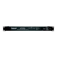
Camera-Mounted ENG/EFP Fiber Optic Transceiver System for JVC GY-HM790HD Camcorder
Brand:
Telecast
| Category:
Transceiver
| Size: 8 MB
Table of Contents
Table of Contents
3
About this User Guide
7
Chapter 1. Important Information
9
Warranty
9
Safety and Fiber Optic Systems
10
Optical Fiber Safety
10
Power Fuses
10
Unpacking and the Copperhead FS-790 Transceiver System
11
Table 1 - What Is Shipped with a Copperhead Fs-790 System
11
Product Returns
12
Chapter 2. - System Overview
13
Fiber Cable Concepts
14
Fiber Optic Cable
14
Fiber Optic Connector Types
15
Figure 3 - Fiber Optic Connectors
15
Table 2 - Fiber Optic Connector Types & Usage
15
Copperhead FS-790 Transceiver System Concepts
16
Signal Paths in the Copperhead FS-790 Transceiver System
17
Figure 4- Base Station to Camera Unit Connection
17
Copperhead FS-790 Transceiver System Components
18
Copperhead KA-F790 Camera Unit Overview
18
Copperhead RM-FP790 Base Station
18
Figure 5 - Camera Unit: Connector Panels
18
Figure 7 - Base Station: Front Indicator Panel
18
Figure 8 - Base Station: Rear Connector Panel
18
Copperhead FS-790 Transceiver System Additional Components
19
Chapter 3. Installation of the Copperhead Ka-F790 Camera Unit on the Jvc Prohd Gy-Hm790 Video Camera
21
Initial Installation of the Copperhead KA-F790 Camera Unit to the Camera
21
Verification of All Components
22
Relocation of the Battery Adaptor from the Camera to the KA-F790 Camera Unit
23
Installation of the Camera Unit Mounting Plate on to the Camera
25
Installation of the Connector Adaptor Plate and Connection of Required Cables
26
Mounting of the Camera Unit on to the Mounting Plate
27
Operational Test of the Installed System
27
Mounting Power Wafer Unit to the Copperhead KA-F790 Camera Unit
28
Figure 10 - Connecting the Power Wafer
28
Relocation of the Copperhead RM-FP790 Base Station Fiber Connector
29
Chapter 4. Copperhead Fs-790 Transceiver System Detailed Description
31
Copperhead KA-F790 Camera Unit
31
Copperhead KA-F790 Camera Unit Connector Area -Connectors
32
Copperhead KA-F790 Camera Unit Indicator and Control Panel
35
Copperhead FS-790 Base Station
37
Copperhead FS-790 Base Station Front Panel
37
Copperhead RM-FP790 Base Station Front Panel - Identifying Controls & Connectors
37
Figure 15 - Fiber Connector Types
37
Copperhead RM-FP790 Base Station Back Panel
41
Copperhead RM-FP790 Base Station Front Panel - Identifying Controls & Connectors
41
External Power Options
41
Internal Power Options
42
Additional Copperhead FS-790 Transceiver System Items
43
Power Wafer" Camera Adaptor
44
MPS External Power Wafer Power Supply
45
Figure 17 - Mps External Power Wafer Power Supply
45
Table 3 - Mps Power Supply Adaptor Options
45
Chapter 5. Connection of the Copperhead Fs-790 Transceiver System
47
Table 4 - Copperhead Fs-790 Power Options
47
Figure 18 - Tactical Fiber between the Base Station and Camera Unit
48
Tactical Fiber between the Base Station and Camera Unit
48
Figure 19 - Smpte Hybrid Fiber between the Base Station (Powered) and Camera Unit
49
SMPTE Hybrid Fiber between the Base Station (Powered) and Camera Unit
49
Figure 20 - Smpte Hybrid Fiber between Base Station and Camera Unit (Infrastructure Wiring)
50
SMPTE Hybrid Fiber between Base Station and Camera Unit (Infrastructure Wiring)
50
Figure 21 - Smpte Hybrid Fiber between the Mps Power Unit and Camera Unit
51
SMPTE Hybrid Fiber between the MPS Power Unit and Camera Unit
51
Connections between the Copperhead RM-FP790 Base Station and the KA-F790 Camera Unit
47
Connections to the Copperhead RM-FP790 Base Station
52
Multi-Pin Cable Assemblies Used with the Copperhead FS-790 Base Station
52
Figure 22 - Copperhead Fs-790 Base Unit Connections
52
Connectors into and out of the Copperhead FS-790 Base Station
53
Connections to the Copperhead FS-790 Camera Unit
55
Connectors into and out of the Copperhead FS-790 Camera Unit Back Side
55
Figure 23 - Copperhead Fs-790 Camera Unit Back Side Connections
55
Camera Unit Connection Example
57
Camera Unit (Camera Facing Side) to Camera Connections
57
Figure 24 - Camera Unit (Camera Facing Side) to Camera Connections
57
Chapter 6. Operation of the Copperhead Fs-790 Transceiver System
59
Set up of the Copperhead FS-790 Transceiver System for Operation
60
Connecting and Managing the Fiber Cable
61
Planning the Fiber Cable Route
61
Running the Fiber Cable
62
Powering the System
64
Powering the Copperhead FS-790 Base Station
64
Powering the Copperhead FS-790 Camera Unit
64
Intercom
65
Figure 25 – Intercom and Tally Controls/Indicators
65
Using the Digital Displays
67
A Brief Guide to Measurement of Fiber Optic Signal Strength
67
The Copperheadfs-790 Base Station Digital Display
67
Standard Operation
71
Shutting down the System
72
Troubleshooting
73
Appendices
74
Appendix 1. Connector Pin Assignments
74
Copperhead FS-790 Base Station Connectors
74
Camera Remote - Base Station DB9 Connector -Wiring
74
Tally/Gpi/Data - Base Station DB15 Connector Wiring
74
Table 5 - Base Station Camera Remote Connector Wiring
74
Table 6 - Base Station Tally/Gpi Connector Wiring
74
Base Station Audio Inputs & Outputs Connector Wiring
75
Power Connector - Base Station 4 Pin XLR Connector Wiring
75
Table 7 - Base Station Audio 25 Pin Connector Wiring
75
Table 8 - Base Station Power Connector Wiring
75
Power Connector - Base Station Fused AC Receptacle
76
Base Station 12VDC Terminal Block Wiring
76
Clear-Com Intercom - Base Station 3 Pin XLR Connector Wiring
76
RTS Intercom - Base Station 3 Pin XLR Connector Wiring
76
Table 9 - Base Station 12Vdc Terminal Block Wiring
76
Table 10 - Base Station Clear-Com Intercom Output Wiring
76
Table 11 - Base Station Rts Intercom Output Wiring
76
Copperhead FS-790 Camera Unit Multi-Pin Connectors
77
Power Wafer - Camera Unit 4 Pin Lemo Connector Wiring
77
Camera Headset - Camera Unit 5 Pin XLR Female Connector Wiring
77
Audio out
77
Table 12 - Camera Unit Power Wafer Connector Wiring
77
Table 13 - Camera Unit Headset Connector Wiring
77
Table 14 - Standard Xlr3 Audio Connector Wiring
77
Appendix 2. Base Station Remote Control Cable
78
Figure 26 - Copperhead Jvc Fp-790 Series Base Station Remote Cable
78
Appendix 3. Audio Cable Wiring Suggestions
79
Copperhead FS-790 Base Station 25-Pin Audio Input Cable
79
Copperhead FS-790 Base Station 25-Pin Audio Output Cable
79
Figure 27 - Copperhead Fp-790 Base Station 25-Pin Audio Input Cable
79
Figure 28 - Copperhead Fp-790 Base Station 25-Pin Audio Output Cable
79
Appendix 4. Specification
80
Appendix 5. Declaration of Conformity
81
Appendix 6. Copperhead Fs-790 System Overview Diagrams
83
Figure 30 - Copperhead Fs-790 Camera Unit Connectors
83
Figure 31 - Copperhead Fs-790 Camera Unit Indicators and Controls
85
Figure 32 - Copperhead Fs-790 Base Station Front Panel
85
Advertisement
Advertisement
Related Products
Telecast CH3-MPS-95VD-2ST-NEU
Telecast CH3-MPS-95VD-2ST-304
Telecast CH3-MPS-95VD-NEU-NEU
Telecast CopperHead
Telecast CopperHead 3400
Telecast CopperHead FS 790
Telecast F-790PSVRG
Telecast FS-790PNACG
Telecast FS-790PNARG
Telecast FS-790PNVCG
Telecast Categories
Multiplexer
Transceiver
Extender
Stereo System
Recording Equipment
More Telecast Manuals
Login
Sign In
OR
Sign in with Facebook
Sign in with Google
Upload manual
Upload from disk
Upload from URL