Sign In
Upload
Manuals
Brands
Tektronix Manuals
Laboratory Equipment
WVR611A
Tektronix WVR611A Manuals
Manuals and User Guides for Tektronix WVR611A. We have
1
Tektronix WVR611A manual available for free PDF download: Service Manual
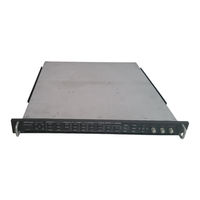
Tektronix WVR611A Service Manual (264 pages)
Waveform Rasterizers
Brand:
Tektronix
| Category:
Laboratory Equipment
| Size: 4 MB
Table of Contents
Table of Contents
5
List of Tables
11
General Safety Summary
15
Service Safety Summary
17
Manual Conventions
19
Manual Structure
19
Preface
19
Related Documents
20
Related Reference Documents
20
Contacting Tektronix
21
Specifications
23
Electrical Specifications
25
Table 1- 1: SDI Input Waveform Vertical Characteristics
25
Table 1- 2: Serial Digital Video (SDI Inputs a and B) Interface Physical Layer Characteristics
26
Table 1- 3: Composite Analog Input Waveform Vertical Characteristics
26
Table 1- 4: Composite Analog Inputs a and B Physical Layer Characteristics
27
Table 1- 5: External Reference Characteristics
29
Table 1- 6: Waveform Sweep (Horizontal) Characteristics
30
Table 1- 7: Waveform Mode Filter Characteristics
31
Table 1- 8: Component Vector Mode
31
Table 1- 9: Composite Vector Mode Characteristics
32
Table 1- 10: Lightning and Diamond Modes Display
32
Table 1- 11: RGB Gamut Error Indication (Diamond Displays)
33
Table 1- 12: Arrowhead Mode (NTSC/PAL Composite Limit Display of Component Input Mode)
33
Table 1- 13: Program Error Alarms and "Background Measurement Alarms
34
Table 1- 14: Miscellaneous Measurements and Displays
35
Table 1- 15: Picture Display Mode
35
Table 1- 16: Measure Display
36
Table 1- 17: Other Display
36
Table 1- 18: Audio Bar Displays
37
Table 1- 19: Audio Bar and Lissajous Displays
39
Table 1- 20: Audio Text Displays
40
Table 1- 21: AES Audio Inputs
40
Table 1- 22: AES Audio Outputs
41
Table 1- 23: Embedded Audio Extraction and Monitoring on Status Bar
42
Table 1- 24: Analog Audio Inputs
43
Table 1- 25: Analog Audio Outputs
44
Table 1- 26: Ground Closure Remote/Ltc Input
46
Table 1- 27: Ethernet Characteristics
46
Table 1- 28: XGA Picture Monitor Output
46
Table 1- 29: General Characteristics
47
Physical Specifications
49
Certifications and Compliances
51
Operating Information
53
Operating Basics
55
Overview
55
Figure 2- 1: a Display with All Four Tiles Visible
55
Figure 2- 2: a Tile in Full-Screen Mode
56
Three Levels of Control
57
Figure 2- 4: a Display with Multiple WFM Displays
57
Tile Settings
58
Figure 2- 5: Display Select Buttons and Fault Indicator
58
Figure 2- 6: Measure Select Buttons
59
Figure 2- 7: Gain Buttons
59
Figure 2- 8: Sweep Buttons
60
Figure 2- 9: Presets Buttons
60
Figure 2- 10: Input Select Buttons
61
Figure 2- 11: General Function Buttons
61
Figure 2- 12: Arrow Keys and SEL Button
61
Pop-Up Menus
62
Figure 2- 13: Control Knobs
62
Figure 2- 14: the WFM Pop-Up Menu with Display Mode Set to Ypbpr
63
Figure 2- 15: the WFM Pop-Up Menu Display Mode Set to RGB
63
Configuration Menu
64
Status Bar
64
Figure 2- 16: the Configuration Menu
64
Figure 2- 17: Elements of the Status Bar
65
Waveform Display
66
Vector Display
67
Figure 2- 18: Waveform Display Elements
67
Figure 2- 19: Vector Display Elements
68
Measure Display
69
Figure 2- 20: Timing Display
69
Picture Display
70
Audio Display
70
Figure 2- 21: Picture Display
70
Figure 2- 22: Audio Display with Phase Display
71
Audio Inputs 3
71
Above-Bar Warning Messages
72
In-Bar Warning Messages
72
Other Display
73
Gamut Display
73
Figure 2- 23: Other Display Elements
73
Figure 2- 24: Gamut Display Elements
74
Status Display
75
Figure 2- 25: a STATUS Display in All Four Tiles
75
Navigating Menus
76
Figure 2- 26: Panes in a Menu
76
Setting the Active Tile
77
Figure 2- 27: Knob Icon
77
Figure 2- 28: Tile Positions in the Display
77
Figure 2- 29: Identifying the Active Tile
78
Figure 2- 30: Press a Numbered Button to Set the Active Tile
78
Displaying a Tile in Full-Screen Mode
79
Figure 2- 31: Full-Screen Mode
79
Selecting a Measurement for the Active Tile
80
Figure 2- 32: Measure Select Buttons
80
Using Online Help
81
Figure 2- 33: the Three Sections of the Online Help
81
Rear Panel Connections
82
Figure 2- 34: Rear-Panel Connectors
82
Table 2- -9: AES Connectors 2
83
Figure 2- -35: Analog I/O Connector Pin Diagram 2
84
Table 2- -11: Channel Pair to Analog Input Mapping 2
85
Figure 2- -36: XGA Output Connector Pin Diagram 2
86
Figure 2- -37: REMOTE Connector Pin Diagram 2
87
Figure 2- -38: RJ-45 Ethernet Connector 2
88
Table 2- -15: Ethernet Connector Pin-Out 2
89
Changing Instrument Settings
91
SDI Input Settings
91
Composite Input Settings
92
External Reference Setting
93
Analog Audio Displays Settings
94
Table 2- -19: Analog Audio Display Settings 2
95
Table 2- -20: Characteristics of Meter Types 2
97
Digital Audio Displays Settings
98
Table 2- -21: Digital Audio Display Settings 2
99
Audio Inputs/Outputs 2
102
Table 2- -22: Audio Inputs and Outputs 2
103
Figure 2- -39: Mapping Inputs to Bars 2
104
Figure 2- -40: Analog out Map 2
105
Figure 2- -42: Bar to Input Mapping 2
106
Figure 2- -44: Video to Audio Mapping 2
107
Gamut Thresholds Menu 2
108
Table 2- -23: Gamut Thresholds 2
109
Display Settings Menu 2
111
LTC / VITC Menu
114
Graticules Menu 2
115
Network Settings 2
116
Figure 2- -46: Setting IP Address 2
117
Figure 2- -47: Setting Subnet Mask 2
118
Figure 2- -48: Setting the Instrument Name 2
120
Figure 2- -49: Setting the SNMP Public Community String 2
121
Figure 2- -50: Setting the SNMP Private Community String 2
122
Figure 2- -51: Setting the SNMP Trap Address 2
123
Utilities Menu 2
124
Figure 2- -52: Viewing Hw/Sw Version Numbers 2
125
Figure 2- -53: Setting the Internal Clock 2
126
Figure 2- -54: CPU Color Palette 2
127
Troubleshooting 6
128
Figure 2- -56: Advanced Diagnostics Dialog Box 2
129
Figure 2- -57: Diagnostics Log 2
130
Updating the Waveform Rasterizer Firmware 2
133
Firmware Package Download 2
134
Figure 2- -59: Transfer Utility Window 2
135
Upgrading Multiple Instruments 2
136
Verifying the Upgrade 2
137
Serial Digital Input 3
141
Recursion and Picture Processing Engine 3
143
Options 7
144
Diagrams 8
145
Advertisement
Advertisement
Related Products
Tektronix WVR610A
Tektronix WVR6100 Series
Tektronix WVR6UP
Tektronix WVR6020
Tektronix WVR6100 Opt. MB
Tektronix WVR5200 Series
Tektronix WVR8300
Tektronix WVR70UP
Tektronix WVR7020
Tektronix WVR7120
Tektronix Categories
Test Equipment
Measuring Instruments
Amplifier
Portable Generator
Printer
More Tektronix Manuals
Login
Sign In
OR
Sign in with Facebook
Sign in with Google
Upload manual
Upload from disk
Upload from URL