Sign In
Upload
Manuals
Brands
Tektronix Manuals
Monitor
WFM700M
Tektronix WFM700M Manuals
Manuals and User Guides for Tektronix WFM700M. We have
2
Tektronix WFM700M manuals available for free PDF download: User Manual
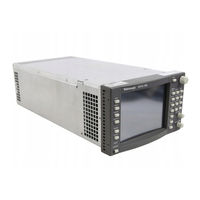
Tektronix WFM700M User Manual (366 pages)
Waveform Monitors
Brand:
Tektronix
| Category:
Measuring Instruments
| Size: 5 MB
Table of Contents
Warranty
3
Table of Contents
6
List of Figures
8
List of Tables
12
General Safety Summary
15
Service Safety Summary
17
Related User Documents
20
Related Reference Documents
20
Contacting Tektronix
21
Getting Started
23
Product Description
25
Platform Features
26
Standard Accessories
31
Table 1- 1: Power Cord Options and Identification
31
Optional Accessories
32
Installation and Power on
35
Hardware Installation
35
Figure 1- 1: Waveform Monitor Chassis
36
Figure 1- 2: WFM7F02 Portable Cabinet
37
Figure 1- 3: WFM7F05 Rack Adapter
38
Connecting Power
39
Packaging for Shipment
40
Functional Check
41
Video-Input Module
43
Functional Checks
44
Figure 1- 4: Accessing the Remote Interface with a Web Browser
56
Operating Basics
65
Functional Overview
67
Front Panel Interface
67
Figure 2- 1: Waveform Monitor Front Panel
67
Table 2- 1: LED Fault Codes
70
Front Panel Buttons
71
Additional Buttons
72
Context-Sensitive Help
76
Rear Panel Connectors
76
Figure 2- 2: Rear Panel View Showing the WFM7M, WFM7A/HD, and WFM7DG Input Modules Installed
76
Multi-Pin Connectors
78
Menus
81
Table 2- 2: Menu Diagram and Reference Information Locator
81
Using the Menu Diagrams
82
Making Menu Selections
82
Figure 2- 3: Example Menu Diagram Showing Components of the Diagram
83
Select Button
83
Audio Menu (Option DG Only)
85
Figure 2- 4: Audio Menu Diagram (Option DG Only)
85
Figure 2- 5: Audio Level Meters Display (Option DG Only)
86
Figure 2- 6: Audio Level Meters + Lissajous Display (Option DG Only)
88
Figure 2- 8: Embedded Audio Status Display
90
Clear Menu
91
Configure Menu
91
Figure 2- 9: Configuration Menu Diagram - Part 1
92
Figure 2- 10: Configuration Menu Diagram - Part 2
93
Figure 2- 11: Configuration Menu Diagram - Part 3
94
Figure 2- 12: Configuration Menu Diagram - Part 4
95
Figure 2- 13: General Alarms Menu Display
96
Table 2- 3: General Alarm Descriptions
97
Table 2- 4: Serial Alarm Descriptions
100
Table 2- 5: Audio Alarm Descriptions (Option DG Only)
101
Figure 2- 14: Mapping AES Inputs to Level Meter Bars
109
Cursor Menu
120
Figure 2- 16: Cursor Menu Diagram
120
Figure 2- 17: Waveform Measurement Cursors
121
Display Menu
123
Figure 2- 18: Display Menu Diagram
123
Eye Menu (WFM700M Only)
126
Figure 2- 19: Eye Menu Diagram
126
Figure 2- 20: 3 Eye Measurement Display with SD Signal
127
Jitter Measurements
128
Figure 2- 21: Jitter Measurement Display
128
Freeze Menu
129
Figure 2- 22: Freeze Menu Diagram
129
Gain Menu
131
Figure 2- 23: Gain Menu Diagram
131
Gamut Menu
132
Figure 2- 24: Gamut Menu Diagram
132
Figure 2- 25: Diamond, Split Diamond, and Arrowhead Measurement Displays
133
Table 2- 6: Variable Ranges for High, Low, and Area Thresholds
134
Help Menu
136
Figure 2- 26: Help Menu Diagram
136
System Information
136
Input Menu
137
Figure 2- 27: Input Menu Diagram
137
Line Select Menu
139
Measure Mode Menu (WFM700A and WFM700HD Only)
141
Measure Mode Menus (WFM700M Only)
141
Bowtie Display
144
Multi Menu
145
Picture Mode
147
Preset Menu
148
Restore Factory
151
Table 2- 7: Factory Default Instrument Settings
151
Print Menu
160
Status Menu
160
Event Logging
164
Sweep Menu
166
Vector Menu
168
Waveform Menu
172
Reference
177
Video Reference
179
Alarms
180
Configuring Alarms
181
Viewing Alarms
181
Table 3- 1: Alarm Icon and Gamut Error Indicator Availability in Major Operating Modes
182
Audio Mode
184
Bowtie Mode
185
Composite Display
187
Data Display (WFM700M Only)
187
Table 3- 2: Data Display Colors
187
Diagnostics
190
Eye / Jitter Mode (WFM700M Only)
192
Freeze Mode
205
Gamut Measurements
206
Diamond Display
208
Line Select Mode
217
Logging
218
Diagnostics Log
218
Table 3- 3: Event Log Error Status Icons
221
Measure Mode (WFM700M Only)
222
Multi Mode
222
Printing
224
Readouts
224
Status Displays
225
Alarm Status Displays
238
Table 3- 4: Alarm Status Indicators
238
Table 3- 5: Alarm Status Display Error Indicators
240
Sweep Mode
241
Vector Mode
243
Lightning Display
247
Table 3- 6: Lightning Graticule Marks
248
Waveform Mode
251
Audio Reference (Option DG Only)
257
Selecting Which Audio Input to Monitor
257
Selecting the Audio Display Type
258
Elements of the Level Meter Audio Display
258
Lissajous (Phase) Display
263
Elements of the Channel Status Display
265
Elements of the Embedded Audio Status Display
269
Configuring the Instrument for Audio Measurements
270
Table 3- 7: Settings in the Audio Inputs/Outputs Configuration Menu
270
Table 3- 8: Settings in the Audio Displays Configuration Menu
271
Table 3- 9: Settings in the Audio Thresholds Configuration Menu
271
Appendices
273
Appendix A: Specifications
275
Electrical Specifications
276
Table A- 1: Waveform Vertical Deflection
276
Table A- 2: Serial Digital Video Interface
278
Table A- -3: Switched Serial Video Output (Serial out
278
Table A- 4: Eye Pattern Display
279
Table A- 5: Jitter Display
280
Table A- -6: Data Error Detection (EDH / Status
281
Table A- 7: Data Display Mode
282
Table A- 8: External Reference
282
Table A- 9: Waveform Horizontal Deflection
283
Table A- 10: Component Vector Mode
283
Table A- 11: Freeze/Capture Funciton
283
Table A- 12: Lightning and Diamond Modes
284
Table A- 13: RGB GAMUT Error Detection
284
Table A- -14: Arrowhead Mode (NTSC/PAL Composite Limit Display
284
Physical Specifications
296
Certifications and Compliances
297
Appendix B: Supported Video Standards
299
Appendix C: Remote Control
301
Ground Closure Interface
301
Remote Web Interface
304
Appendix D: User Service
315
Cleaning
315
Preventive Maintenance
316
Appendix E: Firmware Upgrade
317
Required Equipment
317
Instrument Setup
318
Firmware Upgrade Procedure
322
Appendix F: Cabinet and Rack Adapter Installation
327
Preparation
327
WFM7F02 Portable Cabinet Installation
328
WFM7F03 Plain Cabinet Installation
333
WFM7F05 Rack Adapter Installation
337
Appendix G: Module Installation
347
Preventing Electrostatic Discharge
347
Module Slot Assignments
348
Adding or Replacing a Module
349
Index
357
Advertisement
Tektronix WFM700M User Manual (102 pages)
WFM700 Series Waveform Monitors
Brand:
Tektronix
| Category:
Monitor
| Size: 0 MB
Table of Contents
User Manual
1
Table of Contents
2
General Safety Summary
4
Preface
6
Related Reference Documents
6
Getting Started
8
Product Description
9
Standard Accessories
10
Optional Accessories
12
Installation and Power
13
Hardware Installation
13
Connecting Power
14
Operating Basics
15
Functional Overview
16
Front Panel Knobs and Indicators
17
Front-Panel Buttons
19
Touch Screen (Soft Keys)
20
Readouts
20
Icons
22
Context-Sensitive Help
22
Rear Panel Connectors
23
Menus
26
Making Menu Selections
26
Using the Menu Diagrams
27
Audio Menu (Option DG Only)
28
Configure Menu
29
Cursor Menu
33
Display Menu
34
Eye Menu (WFM700M Only)
35
Freeze Menu
36
Gain Menu
37
Gamut Menu
38
Help Menu
39
Input Menu
39
Line Select Menu
40
Measure Mode Menu (WFM700A and WFM700HD Only)
41
Measure Mode Menu (WFM700M Only)
41
Multi Menu
42
Picture Menu
43
Preset Menu
44
Print Menu
45
Status Menu
45
Sweep Menu
46
Vector Menu
47
Waveform Menu
48
Ancillary Data Display
53
Arib Std-B39 Display
55
Audio Mode (Option Dg Only)
56
Level Meters
57
Bowtie Mode
63
Data Display (Wfm700M Only)
64
Composite Display
64
Eye / Jitter Mode (Wfm700M Only)
66
Gamut Measurements
76
Line Select Mode
80
Measure Mode (Wfm700M Only)
83
Multi Mode
83
Picture Mode
84
Status Displays
86
Vector Mode
89
Waveform Mode
93
Advertisement
Related Products
Tektronix WFM700 Series
Tektronix WFM700HD
Tektronix WFM700A
Tektronix WFM7020
Tektronix WFM7000 Opt. MB
Tektronix WFM70UP FP
Tektronix WFM7200
Tektronix WFM710
Tektronix WFM71UP FP
Tektronix WFM720UP
Tektronix Categories
Test Equipment
Measuring Instruments
Amplifier
Portable Generator
Printer
More Tektronix Manuals
Login
Sign In
OR
Sign in with Facebook
Sign in with Google
Upload manual
Upload from disk
Upload from URL