Sign In
Upload
Manuals
Brands
Tektronix Manuals
Portable Generator
SW503
Tektronix SW503 Sweep Generator Manuals
Manuals and User Guides for Tektronix SW503 Sweep Generator. We have
1
Tektronix SW503 Sweep Generator manual available for free PDF download: Instruction Manual
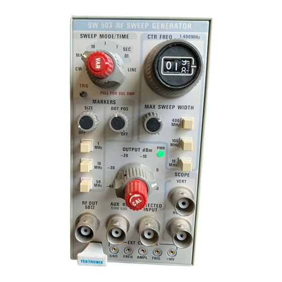
Tektronix SW503 Instruction Manual (68 pages)
Sweep Generator
Brand:
Tektronix
| Category:
Portable Generator
| Size: 5 MB
Table of Contents
Table of Contents
2
Description
6
Introduction
6
Electrical Characteristics
6
Operation
8
Front Panel Controls and Connectors
8
Operating Instructions and Notes
11
General Setup and First-Time Operation
11
Figure 2-2 Typical Operating Setup
11
Cable Connections
12
Impedance Matching
12
Detecting (Demodulating)
12
Figure 2-3 Typical Resistive Pads
12
Figure 2-4 Basic Detector Schematic Diagram
12
Sweep Rate Effects
13
Overloading Effects
13
Low-Level Measurements
13
TV Receiver Interference
13
Use with Digital Counter
13
Operation with X-Y Plotters
13
Figure 2-5 Errors from Sweep Rate Effects
13
Figure 2-6 Markers Selection Switch Location
13
External Control
14
Frequency Control
14
Amplitude Control
14
Trigger Control
14
Figure 2-7 External Control of Frequency
14
Introduction
15
Equipment Required
15
Figure 3-1 SW 503 Rear View
16
Preliminary Steps
16
Procedure
16
Figure 3-3 SW 503 Adjustment Locations, Left Side
17
Figure 3-4 SW 503 Adjustment and Test Points Locations, Right Side
18
Figure 3-5 Normal Interconnections for Calibration
18
Circuit Description
22
General
22
Sweep Ramp Generator
22
Basic Operation
22
Ramp Generator
23
Single Sweep
23
Figure 4-1 SW 503 Sweep Ramp Generator (Simplified Diagram)
23
Line Rate
24
CW Mode
24
Manuai Mode
24
CIRCUIT DESCRIPTION (Cont)
24
Sweep Drive Circuitry
24
Input Adder
24
Ramp Shading Network
24
Figure 4-2 Ramp Shaping Network
25
Output Amplifier
26
Sweep Oscillator Module
26
Figure 4-3 RF Sweep Oscillator Module Block Diagram
26
Figure 4-4 Harmonic Comb Markers Block Diagram
27
Harmonic Marker Module
28
Marker Amplifier
28
Figure 4-5 Counter Interface Signals Sequence
29
Counter Interface
30
Implementing Special Features
31
Changing Horizontal Output Voltage
31
Interface through Rear Connector
31
Introduction
31
Mainframe Modification
31
Vertical Output and Horizontal Output
31
External Frequency Control or Modulation
32
External Amplitude Control or Modulation
32
External Trigger
32
Figure 5-1 Rear Plug-In Connector P40 Interface Wiring
32
Digital Counter Interface
33
Advertisement
Advertisement
Related Products
Tektronix SPG3UP 01
Tektronix SPG6UP 01
Tektronix SPG6UP 02
Tektronix SPG6UP 03
Tektronix SPG70UP
Tektronix SPG 1000
Tektronix SG 5010
Tektronix SG 5030
Tektronix SD-42
Tektronix SC 504
Tektronix Categories
Test Equipment
Measuring Instruments
Amplifier
Portable Generator
Printer
More Tektronix Manuals
Login
Sign In
OR
Sign in with Facebook
Sign in with Google
Upload manual
Upload from disk
Upload from URL