Sign In
Upload
Manuals
Brands
Tektronix Manuals
Accessories
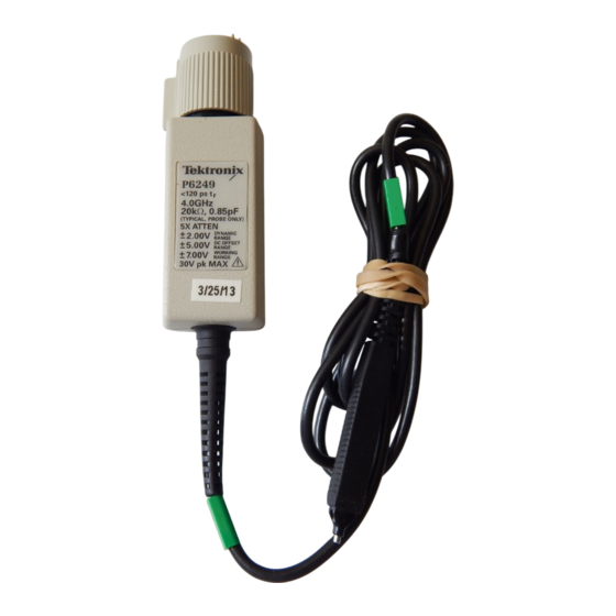
P6249
Tektronix P6249 4GHz Active Probes Manuals
Manuals and User Guides for Tektronix P6249 4GHz Active Probes. We have
1
Tektronix P6249 4GHz Active Probes manual available for free PDF download: Instruction Manual
Tektronix P6249 Instruction Manual (76 pages)
4 GHz 5X Active Probe
Brand:
Tektronix
| Category:
Accessories
| Size: 0 MB
Table of Contents
Table of Contents
5
General Safety Summary
9
Service Safety Summary
11
Contacting Tektronix
12
Product Description
13
Options
13
Standard Accessories
13
Optional Accessories
14
Features and Accessories
15
Features and Standard Accessories
15
Optional Accessories
20
Configuration
21
Probe Offset
21
Figure 1: Dynamic and Offset Limitations
22
Functional Check
23
Figure 2: Probe Functional Check Connections
23
Deskew Fixture
25
Figure 3: Deskew Fixture Connections
25
Probe Calibration Errors
26
Check Compatibility
26
Check for Hardware Problems
27
Operating Basics
29
Handling the Probe
29
Maximum Non-Destructive Input Voltage
29
Input Linear Dynamic Range
29
Ground Lead Length
30
Helpful Hints
31
Low-Inductance Grounding
31
Figure 4: Low-Inductance Grounding
31
Surefoot Grounding
32
Figure 5: Using a Surefoot Adapter for Grounding
32
Probe Tip Test Points
33
Figure 6: Using a Probe Tip as a Test Point
33
Specifications
35
Figure 7: Typical Input Impedance and Phase Versus Frequency
36
Figure 8: Typical Bandwidth
37
Theory of Operation
41
Figure 9: P6249 Simplified Schematic Diagram
41
Probe Head and Cable Assembly
42
Compensation Box
42
Offset Amplifier
42
Probe Identification EEPROM
42
TEKPROBE Interface
43
VCC, +7 V Regulator
43
Figure 10: TEKPROBE Interface
43
Performance Verification
45
Equipment Required
45
Equipment Setup
46
Output Zero
47
Figure 11: Setup for Output Zero and DC Attenuation Accuracy
47
DC Attenuation Accuracy
48
Rise Time
50
Figure 12: Test System Rise Time Setup
50
Figure 13: Test System and Probe Rise Time Setup
51
Adjustments
55
Adjustment Locations
55
Figure 14: P6249 Adjustment Locations
55
Offset Zero
56
Offset Range
57
Figure 15: 1103 Power Supply Offset Voltage Location
57
Figure 16: P6249 Offset Range Setup
58
Maintenance
59
Replacing TEKPROBE Interface Pins
59
Figure 17: Replacing TEKPROBE Interface Pins
59
Removing and Replacing the Compensation Box Covers
60
Figure 18: Removing the Compensation Box Covers
60
Figure 19: Replacing the Compensation Box Cover
61
Removing and Replacing the TEKPROBE Interface Collar
62
Figure 20: Replacing the TEKPROBE Interface Collar
62
Inspection and Cleaning
63
Replacement Parts
63
Preparation for Shipment
63
Troubleshooting
65
Figure 21: Compensation Box Test Point Locations
66
Troubleshooting
67
Replaceable Parts
69
Parts Ordering Information
69
Using the Replaceable Parts List
70
Figure 22: P6249 Replaceable Parts
71
Figure 23: P6249 Standard Accessories
72
Figure 24: P6249 Optional Accessories
74
Advertisement
Advertisement
Related Products
Tektronix P7330
Tektronix P5200A
Tektronix P5202A
Tektronix P5205A
Tektronix P5210A
Tektronix P6013
Tektronix P7225
Tektronix TriMode P7500 Series
Tektronix P6047
Tektronix P6122
Tektronix Categories
Test Equipment
Measuring Instruments
Amplifier
Portable Generator
Printer
More Tektronix Manuals
Login
Sign In
OR
Sign in with Facebook
Sign in with Google
Upload manual
Upload from disk
Upload from URL