Sign In
Upload
Manuals
Brands
Tektronix Manuals
Laboratory Equipment
P3410
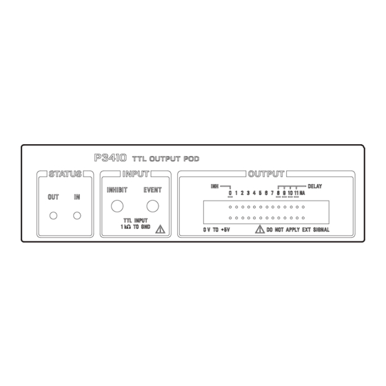
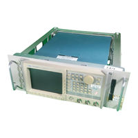
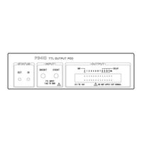
Tektronix P3410 Manuals
Manuals and User Guides for Tektronix P3410. We have
2
Tektronix P3410 manuals available for free PDF download: User Manual, Instructions
Tektronix P3410 User Manual (258 pages)
Data Generator
Brand:
Tektronix
| Category:
Laboratory Equipment
| Size: 4 MB
Table of Contents
Table of Contents
6
Figure 1-1: Pod Connection
12
Figure 2-23: Operating Buttons and Menu Layout
12
Figure 2-24: Pod Connection
12
List of Tables
13
General Safety Summary
16
Service Safety Summary
18
Preface
20
Getting Started
22
Product Description
22
Initial Inspection
23
Options
24
Power Cord Options
24
Accessories
25
Table 1-1: Power Cord Options
25
Table 1-2: Standard Accessories
25
Table 1-3: Standard Accessories for Pods
25
Table 1-4: Optional Accessories
26
Table 1-5: Maintenance Kit Contents
27
Installation
28
Figure 1-2: Yellow Index Mark and Yellow Line for Cable Connection
31
Table 1-6: Power Cord Identification
32
Power on
33
Figure 1-3: Rear Panel Controls Used in Start up
33
Figure 1-4: ON/STBY Switch
34
Start-Up Diagnostics
35
Power off
35
Operating Basics
36
Functional Overview
36
Figure 2-1: Front Panel Overall View
37
Figure 2-2: Front Panel Button Detail
38
Figure 2-3: Rear Panel
39
Figure 2-4: Floppy Disk Drive
40
Figure 2-5: Display Elements
41
Table 2-1: DG2030 Display Elements
42
Figure 2-6: P3410 Front Panel and Rear Panel
43
Figure 2-7: P3420 Front Panel and Rear Panel
44
Internal Structure and Operating Principles
45
Figure 2-8: Hardware Block Diagram
45
Figure 2-9: Inhibit Operation Timing
47
Data Structure Basics
48
Table 2-2: Data Structure Terms
49
Figure 2-10: Data Structure Image
50
Operating Modes Overview
51
Table 2-3: Run Modes
51
Table 2-4: Update Modes
51
Figure 2-11: Menu Buttons and Bezel Buttons
52
Menu Notation
53
Menu Item Display
54
Table 2-5: Bottom Menu Item Display
54
Table 2-6: Side and Sub Menu Item Display
54
Numeric Input
55
Basic Menu Operation
52
Menu Operations
52
Figure 2-12: Numeric Keys, Units Button, Delete Key, and Enter Key
55
Figure 2-13: Numeric Input Using the Numeric Keys
56
Table 2-7: Numeric Input Example
56
Figure 2-15: Knob Icon and Underscore
57
Pattern Data Display Format
58
Figure 2-14: General Purpose Knob and Arrow Buttons
57
Figure 2-16: Timing Display Format
58
Figure 2-18: Binary Display Format
59
Edit Operations
60
Area and Point Cursors
61
Figure 2-17: Table Display Format
59
Figure 2-19: Pattern Data Editing Procedure
61
Figure 2-20: Cursor Display in Editing Operations
62
Text Input
63
Pop up Confirmation Windows
63
Figure 2-21: Character Input Menu
63
Figure 2-22: Popup Confirmation Window
64
Menu Trees
65
Basic Operation Examples
70
Required Equipment
70
Before Starting Examples
71
Operating Procedure Sequences
71
Equipment Connections
72
Figure 2-25: Yellow Index Mark and Yellow Line for Cable Connection
73
Example 1: Creating a Pattern and Storing It in a File
74
Figure 2-26: Binary Pattern Creation
76
Example 2: Loading and Editing a Pattern Stored in a File
77
Figure 2 27: Pattern Edited in Example 2
80
Example 3: Signal Output
81
Figure 2-28: Pod Channel Data Bit Allocation
84
Figure 2-29: Output Voltage Level and Delay Time Display for the P3420 Pod
86
Example 4: Creating a Sequence
89
Reference
102
Operation Outlines
103
Outlines for Pattern Data and Sequence Creations
104
Advanced Control for Sequence
105
Edit Menu
106
Table 3-1: Menu Functions
106
CRT Display
108
Table 3-2: Edit Menu Crt Display
109
File Menu
110
Table 3-3: Import Parameters
112
Table 3-4: Export Parameters
117
Settings Menu
118
Table 3-5: Arrow Button Functions
122
Table 3-6: Pattern Data Display Format
124
Block Menu
125
Table 3-7: Block Relative Cursor Movement
125
Execute Action Menu
129
Table 3-8: Numeric Input Differences
137
Table 3-9: Standard Pattern Data Descriptions
141
Enhanced Action Menu
143
Table 3-10: Parameter Items
144
Table 3-11: Shift Register Generator Parameters
146
Table 3-12: Logical Operation Parameters
149
Table 3-13: Bit Operation Parameters
150
Table 3-14: Serial Code Converter Parameters
152
Table 3-15: Edit Code Table Parameters
153
Table 3-16: Numeric Key Description
154
Make Sequence Menu
155
Undo
161
SETUP Menu
162
Table 3-17: Setup Menu Functions
162
CRT Display
164
Table 3-18: Setup Menu CRT Display
165
Group Assign Menu
166
Pod Assign Menu
169
Table 3-19: Impedance State Contol Methods
170
Level/Delay Menu
171
Pod Control Menu
172
Run Mode Menu
174
Trigger Menu
177
Oscillator Menu
178
APPLICATION Menu
180
UTILITY Menu
182
Table 3-20: Menu Functions
183
Mass Memory Menu
184
Display/Hardcopy Menu
187
System Menu
190
Status Menu
194
Diag Menu
194
Table 3-21: Error Code
195
Appendix A: Performance Characteristics
196
Warranted Characteristics
197
Typical Characteristics
202
Nominal Traits
204
Certification and Compliances
209
Appendix B: Performance Verification
212
Before Running the Operation Tests
213
Test Procedure Notes
215
Self Tests
216
Performance Tests for the Dg2020A/Pod Combination
217
P3410 Pod Performance Test
228
P3420 Pod Performance Test
235
Appendix C: Miscellaneous
244
Repackaging for Shipment
244
Inspection and Cleaning Procedures
245
Factory Settings
247
Conversion Table Examples
249
Index
254
Advertisement
Tektronix P3410 Instructions (3 pages)
Brand:
Tektronix
| Category:
Measuring Instruments
| Size: 0 MB
Table of Contents
Instructions
2
Precaution for Connecting Cable
2
P3410 Front Panel
2
P3420 Front Panel
2
Advertisement
Related Products
Tektronix P7708
Tektronix P7713
Tektronix P7716
Tektronix P7720
Tektronix P3420
Tektronix P7350SMA
Tektronix P3010
Tektronix PWS4205
Tektronix P7360A
Tektronix P6013
Tektronix Categories
Test Equipment
Measuring Instruments
Amplifier
Portable Generator
Printer
More Tektronix Manuals
Login
Sign In
OR
Sign in with Facebook
Sign in with Google
Upload manual
Upload from disk
Upload from URL