Sign In
Upload
Manuals
Brands
Tektronix Manuals
Measuring Instruments
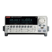
KEITHLEY System SourceMeter 2612B
Tektronix KEITHLEY System SourceMeter 2612B Manuals
Manuals and User Guides for Tektronix KEITHLEY System SourceMeter 2612B. We have
1
Tektronix KEITHLEY System SourceMeter 2612B manual available for free PDF download: Reference Manual
Tektronix KEITHLEY System SourceMeter 2612B Reference Manual (946 pages)
Brand:
Tektronix
| Category:
Measuring Instruments
| Size: 34 MB
Table of Contents
Safety Precautions
3
Welcome
5
Extended Warranty
5
Contact Information
5
Table of Contents
23
In this Section
23
Extended Warranty
23
Contact Information
23
Customer Documentation
24
Organization of Manual Sections
24
Product Software and Drivers
24
Capabilities and Features
25
General Information
26
Displaying the Instrument's Serial Number
26
General Ratings
26
Installation
27
Cooling Vents
27
Starting up Your Instrument
28
Turning the Instrument on and off
28
Placing a Series 2600B in Standby
29
Line Frequency Configuration
29
Fuse Replacement
30
Remote Communications Interfaces
30
Supported Remote Interfaces
30
Remote Interface Connections
31
Usb Communications
32
Communicate with the Instrument
32
LAN Communications
36
Lan Status Leds
37
Using the LAN with Remote Operations
38
Monitoring the LAN
38
Supplied Software
39
Instrument Driver Types
39
Vxipnp Drivers
40
Labview Drivers
40
Getting Instrument Drivers
41
Instrument Driver Examples
41
IVI Shared Components
41
Interchangeable Virtual Instruments (IVI) Style Drivers
42
NI CVI Runtime Engine
42
NI IVI Compliance Package
42
Keithley I/O Layer
43
NI-VISA Runtime
43
Computer Requirements for the Keithley I/O Layer
44
How to Install the Keithley I/O Layer
44
Installation Troubleshooting
45
GPIB Operation
45
GPIB Standards
45
Connect the GPIB Cable
46
Primary Address
47
General Bus Commands
48
Front-Panel GPIB Operation
51
Error and Status Messages
51
Communication Status Indicators
51
LOCAL Key
52
Interface Operation
52
Setting RS-232 Interface Parameters
53
Remote RS-232 Parameters
53
Sending and Receiving Data
54
Data Bits and Parity
54
Flow Control and Signal Handshaking
54
System Information
56
Instrument Description
57
In this Section
57
Controls, Indicators, and Connectors
57
Front Panel
57
Power Switch, Display and Configuration Keys
58
SMU Setup, Performance Control, Special Operation, and Numbers
59
Range Keys
60
Cursor Keys
60
Navigation Wheel
61
Output Control
61
Display Indicators (Not Shown)
61
Rear Panel
62
SMU Connector
65
Cooling Exhaust Vents
66
Power Module
67
Menu Overview
68
Menu Navigation
68
Menu Trees
68
Configuration Menus
71
Setting Source and Compliance Values
75
Beeper
76
Displayed Error and Status Messages
77
Display Operations
77
Display Mode
77
Display Functions and Attributes
78
Display Features
78
Display Messages
80
Clearing the Display
80
Cursor Position
81
Displaying Text Messages
82
Character Codes
82
Returning a Text Message
83
Input Prompting
84
Parameter Value Prompting
84
Local Lockout
87
Load Test Menu
87
Adding USER TESTS Menu Entries
88
Deleting USER TESTS Menu Entries
89
Running a Test from the Front Panel
89
Capturing Key-Press Codes
89
USB Storage Overview
91
Connecting the USB Flash Drive
91
File System Navigation
92
Sourcing and Measuring
93
Basic Operation
93
Operation Overview
93
Source-Measure Capabilities
94
Voltage and Current
94
Setting the Limit
96
Front-Panel Limit
96
Remote Limit
96
Sink Operation
97
Sink Mode
97
Setting the Sink Mode Using the Front Panel
98
Setting the Sink Mode from the Remote Interface
98
Fundamental Circuit Configurations
98
Operation Considerations for the ADC
99
Front-Panel Autozero
100
Remote Command Autozero
100
NPLC Caching
100
Step 3: Select the Measurement Function and Range
102
Step 5: Observe Readings on the Display
102
Remote Source-Measure Commands
103
Requesting Readings
103
Source-Measure Programming Example
104
Triggering in Local Mode
104
Configuring Trigger Attributes in Local Mode
105
Front-Panel Triggering Example
106
Configuring for Measure-Only Tests Using the MODE Key
106
V-Meter and I-Meter Measurements
107
Ohms Ranging
108
Basic Ohms Measurement Procedure
108
Remote Ohms Command
109
Ohms Programming Example
109
Ohms Sensing
110
Power Measurements
111
Basic Power Measurement Procedure
112
Power Measurements Using the Remote Interface
112
Remote Power Reading Command
113
Power Measurement Programming Example
113
Contact Check Measurements
114
Contact Check Commands
115
Contact Check Programming Example
115
Saved Setups
116
Saving User Setups
116
Recalling a Saved Setup
117
Start-Up Configuration
117
Saving User Setups from a Remote Interface
117
Restoring the Factory Default Setups
118
Start-Up (Power-On) Configuration
118
DUT Test Connections
119
Input/Output Connectors
119
Input/Output LO and Chassis Ground
121
Wire Local Sensing Connections
124
Wire Remote Sensing Connections
124
Contact Check Connections
126
Multiple SMU Connections
126
Combining SMU Outputs
129
Combining Channels in Series to Output Higher Voltage
133
Combining Channels in Parallel to Output Higher Current
134
Guarding and Shielding
135
Safety Shield
135
Safety Shielding and Hazardous Voltages
135
Noise Shield
139
Using Shielding and Guarding Together
140
Test Fixture
141
Floating a SMU
142
DUT Connection Settings
144
Sense Mode Selection
144
Front Panel Sense Mode Selection
144
Output-Off States
145
High-Impedance Output-Off Mode
146
Zero Output-Off Mode
146
Output-Off Function
147
Selecting the Output-Off Function
147
Output-Off Limits (Compliance)
148
Setting Output-Off Limits
148
Remote Programming Output-Off States Quick Reference
149
Range
149
Available Ranges
149
Maximum Source Values and Readings
150
Measure Auto Delay
150
Ranging Limitations
150
Manual Ranging
151
Low Range Limits
151
Range Considerations
152
Range Programming Example
154
Digits
154
Setting Display Resolution from the Front Panel
154
Setting Display Resolution from a Remote Interface
155
Digits Programming Example
155
Speed
155
Setting Speed
156
Front-Panel Speed Configuration
156
Remote Speed Programming
156
Sweep Operation
157
Sweep Characteristics
158
Linear Staircase Sweeps
158
Logarithmic Staircase Sweeps
160
List Sweeps
163
Pulse Mode Sweeps
164
Pulse Duty Cycle
165
Pulsing in the Extended Operating Area (EOA)
165
Configuring and Running Sweeps
166
Sweeping Using Factory Scripts
167
Sweep Programming Examples
168
Linear Staircase Sweep Example
168
Pulse Current Sweep Example
169
List Sweep Example
169
Relative Offset
169
Defining a Relative Offset Value
170
Relative Offset Programming Example
171
Filters
172
Filter Types
172
Response Time
173
Configuring the Filter
173
Filter Programming Example
174
Understanding High-Capacitance Mode
175
Understanding Source Settling Times
176
Adjusting the Voltage Source
177
Understanding the Capacitor
177
Charging the Capacitor and Taking Readings
177
Enabling High-Capacitance Mode
178
Command Interface
178
Measuring Current
179
Script Example
179
In this Section
181
Front-Panel Reading Buffer Control
181
Reading Buffer Options
182
Configuring Reading Buffers
183
Appending or Overwriting Existing Reading Buffers
184
Storage Operation
184
Saving Reading Buffers
185
Saving the Reading Buffers to Nonvolatile Memory
185
Saving the Reading Buffer to a USB Flash Drive
185
Recalling Readings
186
Remote Reading Buffer Programming
187
Dedicated Reading Buffer Designations
187
Reading Buffer Commands
188
Buffer Storage Control Attributes
189
Buffer Storage Control Programming Examples
190
Buffer Read-Only Attribute Programming Examples
190
Statistic Attributes
191
Reading Buffer Attributes
192
Buffer Status
193
Dynamic Reading Buffers
193
Dual Buffer Example
195
Dynamically Allocated Buffer Example
196
In this Section
197
Remote Triggering Overview
197
Using the Remote Trigger Model
199
Configuring Source and Measure Actions
202
Enabling Pulse Mode Sweeps Using the End Pulse Action
203
SMU Event Detectors
204
Clearing SMU Event Detectors
204
Using the TRIG Key to Trigger a Sweep
205
Using Trigger Events to Start Actions on Trigger Objects
206
Action Overruns
206
Digital I/O Port and TSP-Link Synchronization Lines
207
Common Attributes
207
Trigger Configuration on Hardware Lines
208
Action Overruns on Hardware Lines
209
Timers
209
Timer Attributes
209
Timer Delays
209
Pass-Through Mode
210
Triggering a Timer
210
Assigning the Stimulus Attribute
210
Timer Action Overruns
211
Using Timers to Perform Pulse Mode Sweeps
211
Single Pulse Example Code
213
Pulse Train Example Code
215
Event Blenders
216
Event Blender Modes
216
Assigning Input Trigger Events
216
LAN Triggering Overview
217
Understanding Hardware Value and Pseudo Line State
217
Understanding LXI Trigger Event Designations
218
Generating LXI Trigger Packets
218
Command Interface Triggering
218
Trigger Generator
219
Manual Triggering
219
Interactive Triggering
219
Detecting Trigger Events Using the Wait Function
220
Using the Assert Function to Generate Output Triggers
220
Using the Release Function of the Hardware Lines
221
Using the Set Function to Bypass SMU Event Detectors
221
Event Detector Overruns
222
Manual Triggering Example
223
Digital I/O Triggering Interactive Example
223
Hardware Trigger Modes
224
Falling Edge Trigger Mode
224
Rising Edge Master Trigger Mode
225
Rising Edge Acceptor Trigger Mode
226
Either Edge Trigger Mode
227
Understanding Synchronous Triggering Modes
228
Synchronous Master Trigger Mode (Synchronousm)
228
Synchronous Acceptor Trigger Mode (Synchronousa)
229
Synchronous Trigger Mode
230
Digital I/O
231
Port Configuration
231
Digital I/O Lines
232
Output Enable Line
232
Interlock Line
233
Digital I/O Configuration
233
Controlling Digital I/O Lines
234
Digital I/O Bit Weighting
235
Remote Digital I/O Commands
235
Digital I/O Programming Example
236
Using Output Enable
236
Front-Panel Control of Output Enable
237
Remote Control of Output Enable
238
Operation
239
Connecting to the TSP-Link System
239
Theory of Operation
241
In this Section
241
Analog-To-Digital Converter
241
Source-Measure Concepts
241
Overheating Protection
242
Power Equations to Avoid Overheating
242
General Power Equation
243
Maximum Duty Cycle Equation
243
Continuous Power Operating Boundaries
244
Operation as a Sink
246
V-Source Operating Boundaries
246
Load Considerations (V-Source)
248
V-Source Sink Operating Boundaries
250
I-Source Operating Boundaries
252
Load Considerations (I-Source)
254
I-Source Sink Operating Boundaries
257
Source I Measure I, Source V Measure
260
Measure Only (Voltage or Current)
261
Contact Check
262
Guard Connections
263
Measurement Settling Time Considerations
265
For Controlling Settling Time Delay
266
Effects of Load on Current Source Settling Time
266
Creating Pulses with the Series 2600B
267
Pulse Rise and Fall Times
267
Range and Pulse Settling
268
Load and Operating Mode
268
Pulse Width
268
Maintenance
269
In this Section
269
Line Fuse Replacement
269
Front Panel Tests
271
Display Patterns Test
272
Upgrading the Firmware
272
Introduction to TSP Operation
275
Controlling the Instrument by Sending Individual Command Messages
275
Information on Scripting and Programming
277
About TSP Commands
277
Beeper Control
278
Bit Manipulation and Logic Operations
278
Data Queue
279
Error Queue
280
Event Log
280
Instrument Identification
282
Parallel Script Execution
284
Queries and Response Messages
284
Reading Buffer
285
SMU Calibration
288
Running a Factory Script
294
Retrieving and Modifying a Factory Script Listing
295
Kisweep Factory Script
295
Kipulse Factory Script
296
Kihighc Factory Script
297
Kiparlib Factory Script
298
Kisavebuffer Factory Script
298
Instrument Programming
299
In this Section
299
Fundamentals of Scripting for TSP
299
What Is a Script
300
Run-Time and Nonvolatile Memory Storage of Scripts
300
What Can be Included in Scripts
301
Commands that Cannot be Used in Scripts
301
Manage Scripts
301
Create a Script Using TSB Embedded
305
Run Scripts
306
Run the Anonymous Script
306
Run a Named Script
306
Scripts that Run Automatically
308
Autorun Scripts
308
Autoexec Script
308
Working with Scripts in Nonvolatile Memory
309
Save a User Script
309
Save the Anonymous Script as a Named Script
310
Delete User Scripts
311
Fundamentals of Programming for TSP
314
What Is Lua
314
Lua Basics
314
Function and Variable Name Restrictions
315
Values and Variable Types
316
Variable Types
317
Delete a Global Variable
318
Create Functions Using the Function Keyword
319
Create Functions Using Scripts
320
Group Commands Using the Function Keyword
321
Logical Operators
322
String Concatenation
322
Operator Precedence
323
Conditional Branching
324
Loop Control
325
While Loops
325
Repeat until Loops
326
For Loops
327
Standard Libraries
330
Base Library Functions
331
Lua Memory Management
331
String Library Functions
332
Math Library Functions
333
Programming Example
334
Test Script Builder (TSB)
334
Installing the TSB Software
334
Installing the TSB Add-In
335
Using Test Script Builder (TSB)
335
Project Navigator
337
Script Editor
337
Outline View
337
Programming Interaction
338
Password Management
338
Password Overview
339
Setting the Password from a Command Interface
339
Unlocking the Remote Interface
340
Resetting the Password
340
Working with TSB Embedded
341
Sending Instrument Commands with TSB Embedded
341
Advanced Scripting for TSP
342
Global Variables and the Script.user.scripts Table
342
Create a Script Using the Script.new Command
344
Create an Unnamed Script Using Script.new
344
Rename a Script
346
Retrieve a User Script
348
Retrieve Source Code One Line at a Time
348
Retrieve a Script as a Single String
349
Retrieve a Script Using TSB Embedded
349
Delete User Scripts from the Instrument
349
Restore a Script to the Run-Time Environment
350
Memory Considerations for the Run-Time Environment
351
TSP-Link System Expansion Interface
352
Master and Subordinates
353
TSP-Link Nodes
353
Assigning Node Numbers
354
Resetting the TSP-Link Network
355
Front Panel Operation
355
Remote Programming
355
Using the Reset Command
357
Using the Abort Command
357
Triggering with TSP-Link
357
TSP Advanced Features
358
Using Groups to Manage Nodes on TSP-Link Network
360
Master Node Overview
360
Group Leader Overview
360
Assigning Groups
361
Running Simultaneous Test Scripts
361
Coordinating Overlapped Operations in Remote Groups
361
Using the Data Queue for Real-Time Communication
362
Copying Test Scripts Across the TSP-Link Network
363
Removing Stale Values from the Reading Buffer Cache
363
TSP-Net
364
TSP-Net Capabilities
364
Using TSP-Net with any Ethernet-Enabled Instrument
365
Example Script
366
TSP-Net Compared to TSP-Link to Communicate with TSP-Enabled Devices
367
TSP-Net Instrument Commands: General Device Control
367
TSP-Net Instrument Commands: TSP-Enabled Device Control
367
Example: Using Tspnet Commands
368
In this Section
369
TSP Command Programming Notes
369
Placeholder Text
369
Syntax Rules
370
Time and Date Values
370
Command Name and Summary Table
372
Command Usage
373
Command Details
373
Example Section
374
Related Commands and Information
374
TSP Commands
375
Display Screen
446
Format.data
468
Gpib.address
475
Serial.databits
555
Serial.flowcontrol
556
Serial.parity
557
Bit B7 B6 B5 B4
712
Binary Value
712
Decimal
712
Weights
712
Example
713
Status.standard.exe
714
Status.standard.enable = Standardregister
715
Example 1
718
Troubleshooting Guide
783
Effects of Errors on Scripts
784
Retrieving Errors
784
Error Summary List
784
LAN Troubleshooting Suggestions
789
Frequently Asked Questions
791
How Do I Display the Instrument's Serial Number
791
How Do I Optimize Performance
792
Disabling Autozero to Increase Speed
792
How Do I Upgrade the Firmware
792
How Do I Use the Digital I/O Port
793
How Do I Trigger Other Instruments
793
Triggering a Scanner
793
Interactive Trigger Programming
794
More Information about Triggering
794
How Do I Generate a GPIB Service Request
794
Setting up a Service Request
794
Service Request Programming Example
795
Polling for Srqs
795
How Do I Store Measurements in Nonvolatile Memory
795
When Should I Change the Output-Off State
796
How Do I Make Contact Check Measurements
796
How Do I Make Low-Current Measurements
797
Low-Current Connections
797
Low-Current Measurement Programming Example
799
How Can I Change the Line Frequency or Voltage
799
Where Can I Get the Labview Driver
799
What Should I Do if I Get an 802 Interlock Error
800
Why Is the Reading Value 9.91E37
800
Next Steps
801
Additional Series 2600B Information
801
In this Appendix
803
Verification Test Requirements
804
Recommended Verification Equipment
805
Restoring Factory Defaults
806
Performing the Verification Test Procedures
807
Test Considerations
807
Setting the Source Range and Output Value
808
Setting the Measurement Range
808
Current Source Accuracy
809
Current Measurement Accuracy
812
Voltage Source Accuracy
815
Voltage Measurement Accuracy
816
Adjustment Considerations
819
Calibration Adjustment Cycle
820
Recommended Calibration Adjustment Equipment
820
Calibration Adjustment Overview
821
Calibration Commands Quick Reference
823
Calibration Adjustment Procedure
825
LAN Concepts and Settings
839
In this Appendix
839
Establishing a Point-To-Point Connection
840
Step 1: Identify and Record the Existing IP Configuration
841
Step 2: Disable DHCP to Use the Computer's Existing IP Address
842
Step 3: Configure the Instrument's LAN Settings
847
Step 4: Install the Crossover Cable
848
Step 5: Access the Instrument's Web Page
849
Connecting to the LAN
849
Setting the LAN Configuration Method
849
Setting the Ip Address
850
Setting the Gateway
850
Setting the Subnet Mask
851
Configuring the Domain Name System (DNS)
851
LAN Speeds
852
Duplex Mode
853
Viewing LAN Status Messages
853
Viewing the Network Settings
854
Confirming the Active Speed and Duplex Negotiation
855
Confirming Port Numbers
855
Selecting a LAN Interface Protocol
856
Raw Socket Connection
856
Dead Socket Connection
856
Configuring a Telnet Connection
857
Logging LAN Trigger Events in the Event Log
860
Accessing the Event Log from the Command Interface
861
Common Commands
863
In this Appendix
863
Command Summary
863
Script Command Equivalents
864
Identification Query: *IDN
865
Operation Complete and Query: *OPC and *OPC
865
Self-Test Query: *TST
866
Wait-To-Continue: *WAI
866
Status Model
867
Status Register Set Contents
867
Command Queue
869
Output Queue
869
Status Function Summary
870
Status Model Diagrams
871
Clearing Registers
880
Programming and Reading Registers
880
Programming Enable and Transition Registers
880
Reading Registers
881
Status Byte and Service Request (SRQ)
881
Status Byte Register
882
Service Request Enable Register
884
Serial Polling and SRQ
884
SPE, SPD (Serial Polling)
885
Status Byte and Service Request Commands
885
Enable and Transition Registers
885
Controlling Node and SRQ Enable Registers
886
Status Register Sets
886
System Summary Registers
886
Standard Event Register
887
Operation Status Registers
888
Questionable Status Registers
890
Measurement Event Registers
891
Register Programming Example
892
TSP-Link System Status
892
Status Model Configuration Example
893
Status Configuration (Enable) Commands
893
In this Appendix
895
Series 2600B Display Character Codes
895
Model 2400 Emulation
901
Model 2400 Compatibility
903
Status Word
904
Logarithmic Sweep
905
Digital I/O Mapping
905
Model 2400 SCPI Command Support
906
Model 2400 SCPI Command Compatibility
914
Advertisement
Advertisement
Related Products
Tektronix KEITHLEY 2614B
Tektronix KEITHLEY System SourceMeter 2611B
Tektronix Keithley 2601B-PULSE
Tektronix KEITHLEY 2604B
Tektronix KEITHLEY 2634B
Tektronix Keithley 2651A
Tektronix KEITHLEY SourceMeter 2606B
Tektronix 2630
Tektronix 2642A
Tektronix KEITHLEY System SourceMeter 2636B
Tektronix Categories
Test Equipment
Measuring Instruments
Amplifier
Portable Generator
Printer
More Tektronix Manuals
Login
Sign In
OR
Sign in with Facebook
Sign in with Google
Upload manual
Upload from disk
Upload from URL