Sign In
Upload
Manuals
Brands
Tektronix Manuals
Test Equipment
CSA 907T
Tektronix CSA 907T Manuals
Manuals and User Guides for Tektronix CSA 907T. We have
1
Tektronix CSA 907T manual available for free PDF download: User Manual
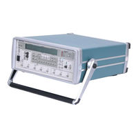
Tektronix CSA 907T User Manual (142 pages)
Bit Error Rate Test Set
Brand:
Tektronix
| Category:
Test Equipment
| Size: 5 MB
Table of Contents
Table of Contents
8
List of Figures
12
Figure 2-6: the Error Detector ERROR HISTORY Section
13
Figure 3-17: the ERROR DETECTION Section
13
List of Tables
14
CSA 907A Description
16
Operation with a Continuous Clock
17
Figure 1-1: Basic System Connections
17
Burst Mode Operation
18
CSA 907A Pattern Generator Description
18
Installation
20
Safety
20
Installation
21
Figure 1-4: Location of Power Cord Connector and Fuse Holder on Rear Panel (CSA 907A Error Detector Shown)
23
Operating Basics
27
Tutorial
27
Figure 2-3: the Pattern Generator PATTERN Section
28
Figure 2-4: the Error Detector SYNC Section
29
Figure 2-5: the Error Detector ERROR DETECTION Section
29
Advanced Pattern Generator Example
30
Figure 2-7: the Pattern Generator CLOCK Section
31
Figure 2-8: Clock Frequency Readout on the Pattern Generator
31
Figure 2-9: the Pattern Generator ERROR INJECT Section
32
Advanced Error Detector Example
33
CSA 907A Pattern Generator Front and Rear Panels
36
CSA 907A Error Detector Front and Rear Panels
38
Error Detector Inputs
40
Input Connectors
40
Figure 3-1: the Error Detector INPUT Section
40
Input Controls
41
Table 3-1: Lnput Control Assignments
42
Pattern Generator Outputs
44
Figure 3-2: the Pattern Generator OUTPUT Section
44
Figure 3-4: Output Readouts on the Pattern Generator Display
45
Table 3-3: Effect of Load Termination on Baseline Offset
46
Figure 3-7: the Pattern Generator CLOCK Section
48
Figure 3-8: Clock Frequency Readouts on the Pattern Generator
50
Figure 3-9: the Pattern Generator OUTPUT Section
50
Clockoutputs
51
Figure 3-10: Clock Output Readouts on the Pattern Generator
51
Pattern Generator Output Connectors
51
Figure 3-13: the Word Menu (Error Detector Shown)
54
Table 3-5: Synchronization Thresholds
55
Table 3-6: SONETIFDDI Pattern Locations
57
Figure 3-14: the Pattern Generator ERROR INJECT Section
60
Figure 3-15: the Pattern Generator Display
60
Figure 3-16: Location of the Error Lnject Connector on the Pattern Generator Rear Panel
61
Figure 3-18: the Bit Error Rate Readout on the Display
63
Figure 3-19: Error Detector Test Menu
64
Figure 3-20: Error Detector Window Menu
67
Csa 907A
70
Table 3-7: Electrical Characteristics for DATA. CLOCK. and
72
Table 4-1: CSA 907A Pattern Generator Specifications
92
Table 4-2: CSA 907A Error Detector Specifications
94
Table 4-3: CSA 907A Pattern Generator and
96
Table 4-4: CSA 907A Pattern Generator Factory Default Settings
98
Table 4-5: CSA 907A Error Detector
99
Table 4-6: Recommended Test Equipment
102
Table 4-7: Connections for Functional Test
104
Table 4-8: Data Levels
107
Table 4-9: Error Detector Termination Threshold Limits
110
Table 4-1 1: Pattern Generator Clock Frequency Limits
114
Table 4-15: Word Patterns and Frequency Values
116
Table 4-17: Pattern Generator Data Amplitude
118
Table 4-18: Pattern Generator Data Baseline Offset
118
Table 4-19: Connections for Clock Output Amplitude and Baseline Offset Check
119
Table 4-20: Pattern Generator Clock Amplitude
120
Table 4-22: Connections for External Error Injection Check
121
Table 4-23: Error Injection Rate
123
Table 4-24: Connections for Monitor Output Check
124
Advertisement
Advertisement
Related Products
Tektronix CSA8000B Series
Tektronix CSA8200 Series
Tektronix CSA8000 Series
Tektronix CSA 907A
Tektronix CMD 80
Tektronix CA PLUG-IN
Tektronix CTRL7100 Series
Tektronix SONET CTS 710
Tektronix CTS 710
Tektronix CSA7UP
Tektronix Categories
Test Equipment
Measuring Instruments
Amplifier
Portable Generator
Printer
More Tektronix Manuals
Login
Sign In
OR
Sign in with Facebook
Sign in with Google
Upload manual
Upload from disk
Upload from URL