Sign In
Upload
Manuals
Brands
Tektronix Manuals
Measuring Instruments
7L13
User Manuals: Tektronix 7L13 Spectrum Analyzer Plug-In
Manuals and User Guides for Tektronix 7L13 Spectrum Analyzer Plug-In. We have
1
Tektronix 7L13 Spectrum Analyzer Plug-In manual available for free PDF download: Instruction Manual
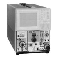
Tektronix 7L13 Instruction Manual (72 pages)
Spectrum
Brand:
Tektronix
| Category:
Measuring Instruments
| Size: 6 MB
Table of Contents
Table of Contents
3
General Information & Specifications
7
Electrical Characteristics
8
Environmental Characteristics
10
Operating Instructions
11
Introduction
11
Function of the Front Panel Controls
11
Operational Check
15
Using the Analyzer
19
Signal Application
19
Resolution, Sensitivity, and Frequency Span
20
Gain Desensitization Near 0 Hz
21
Using the Video Filter
21
Selecting Sweep Rate
21
Triggering the Display
22
Manual Scan of the Spectrum
22
External Trigger Operation
22
Using the CAL out Signal Reference for Accurate
23
Frequency and Amplitude Measurements
23
Using the Analyzer below 100 Khz
24
Performance Check
25
Operational Performance and Instrument Familiarization
25
Equipment Required
25
Preliminary Preparation
25
Check the 10 Db/DIV and LIN Mode Calibration
25
Check the Frequency Readout Accuracy
26
Check the Range of the REF VAR Control, the
26
Check the Operation of the Video Filters
27
Check Sensitivity
27
Check Spurious Signals from Internal Sources
29
Check Incidental Wing
30
MANUAL, and off Positions
31
Equipment Required
31
Check the Calibrator Frequency
33
Check RF Attenuator Accuracy
34
Check Display Flatness
34
Check Intermodulation Distortion
35
Check Pulse Stretcher Operation
36
Check Triggering Operation and Sensitivity
37
Check the External Horizontal Input Voltage Requirement
38
Check the Video Output Level
39
Check Frequency Span Accuracy and Linearity
39
Check Time/DIV Accuracy
40
CALIBRATION Page
43
Equipment Required
43
Short Form Procedure and Record
43
Time Base Section
45
Adjust Sweep Length, Offset, and Triggering
45
Function if Alignment
48
Adjust the LIN Mode Baseline Offset
48
Adjust the Gain Compensation and Calibrate the Reference Level
48
1St lo Phase Lock Loop
50
Error Amplifier Offset Adjustment
50
Frequency Span and 1St lo Calibration
50
Adjust the Frequency Span of the 1St lo and the 16-19 Mhz Oscillators
50
Calibrate the Center Frequency and Frequency Readout
52
Adjust Memory Gain
53
Adjust Error Amplifier Gain
53
Resolution
53
Adjust the Error Amplifier Gain
53
Adjust the Memory Gain
53
Adjust the Bandpass of the 105 Mhz if Amplifier and 300 Khz Filter
54
Adjust the Resolution Gain Leveling Compensation
56
Adjust the Post Resolution Amplifier Gain
58
Minimize Intermodulation Products
58
50 Mhz Calibrator
58
Adjust the Calibrator Output
58
Circuit Description
61
Block Diagram Description
61
Detailed Circuit Description
62
RF or Microwave Circuits
62
Phase Lock and Frequency Stablization
63
YIG Driver, Voltage Memory and Phase Lock Logic
64
Frequency Tuning Control and Readout
65
Tuning Control
65
YIG Driver
65
Frequency Span
66
Marker Generator
66
105 Mhz if Amplifier, 3Rd Mixer and Oscillator
66
10 Mhz if Pre-Resolution Amplifier and
66
YIG Oscillator Power Supply
67
30 Hz Filter
67
50 Mhz Calibrator
67
Function if Amplifier
67
Video Filter, Pulse Stretcher, Baseline Clipper
68
Vertical Output
68
Frequency Readout
69
Uncal Circuit
71
Sweep Triggering Sweep Generator and Horizontal Amplifiers
72
Advertisement
Advertisement
Related Products
Tektronix 7L12
Tektronix 7D20
Tektronix 7D01
Tektronix 7L5
Tektronix 7853A
Tektronix 7853AN
Tektronix Keithley 7711
Tektronix 7L18
Tektronix 7D02
Tektronix 7K14
Tektronix Categories
Test Equipment
Measuring Instruments
Amplifier
Portable Generator
Printer
More Tektronix Manuals
Login
Sign In
OR
Sign in with Facebook
Sign in with Google
Upload manual
Upload from disk
Upload from URL