Sign In
Upload
Manuals
Brands
Tektronix Manuals
Amplifier
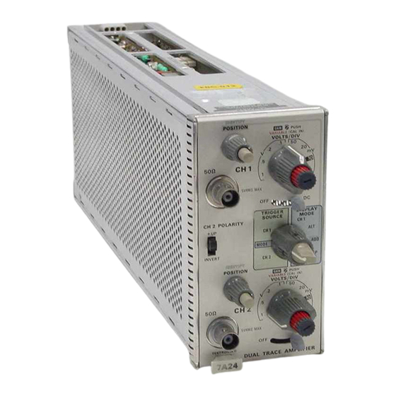
7A24
Tektronix 7A24 Manuals
Manuals and User Guides for Tektronix 7A24. We have
4
Tektronix 7A24 manuals available for free PDF download: Instruction Manual
Tektronix 7A24 Instruction Manual (78 pages)
Dual Trace Amplifier
Brand:
Tektronix
| Category:
Amplifier
| Size: 3 MB
Table of Contents
Table of Contents
4
Safety Information
6
Position
7
Release Latch
8
Coupling
8
Display Mode
8
Checkout Procedure
10
Detailed Operating Information
10
Input Coupling
10
Introduction
10
Signal Connections
10
Vertical Gain Check and Adjustment
10
Display Modes
11
Input Protection Fuse
11
POLARITY Switching
11
Trigger Modes
11
Vertical Deflection Factor
11
TRACE Identification
12
Basic Applications
12
General
12
Peak-To-Peak Voltage Measurements
12
Section 1 Operating Instructions
8
Controls and Connectors
8
Functional Check
8
Setup Procedure
8
Measuring the Peak-To-Peak Voltage
12
Instantaneous Voltage Measurements
13
Comparison Measurements
13
Measuring Instantaneous Voltage with
13
Dual Trace Phase Difference Measurements
14
High Resolution Phase Measurements
15
Common Mode Rejection
15
High Resolution Phase Measurement Using
15
Using the ADD Mode for Common-Mode Rejection
16
Section 2 Specification
17
Electrical
17
Environmental
18
Physical
18
Section 3 Theory of Operation
19
Introduction
19
Block Diagram
19
1 And Ch 2 Atienuators
19
Ch 1 and Ch 2 Amplifiers
20
Display Switching and Output
20
Ch 1 and Ch 2 Readout
21
Lubrication Procedure for a Typical Cam Switch
22
Section 4 Maintenance
22
Preventive Maintenance
22
Cleaning
22
General
22
Lubrication
22
Color Code for Resistors and Capacitors
23
Troubleshooting
24
General
24
Troubleshooting Aids
24
Semiconductor Electrode Configurations
24
TROUBLESHOOTING Equipment
25
Troubleshooting Procedure
25
Orientation of Multi-Connector Holders
25
Corrective Maintenance
27
General
27
Obtaining Replacement Parts
27
Soldering Techniques
27
Circuit Board Removal
28
Component Replacement
28
Fuse and Atienuator Replacement
28
Semiconductor Replacement
28
Interconnecting Pins
29
Switch Replacement
29
Coaxial End-Lead Connector Assembly
29
Readjustment after Repair
30
Repackaging for Shipment
30
Exploded View of Circuit-Board Pin and Ferrule
30
Section 5 Performance Check and Adjustment
31
Preliminary Information
31
Adjustment Interval
31
Special Calibration Fixtures
31
TEKTRONIX FIELD Service
31
Test Equipment Alternatives
31
TEST EQUIPMENT Required
31
Using this Procedure
31
Preliminary Procedure
34
Index to Performance Check and Adjustment Procedure
34
1 Check Readout and IDENTIFY
35
J 2. Check/Adjust Input Resistance
35
Low Frequency Procedure
35
3 Adjust Offset Current
36
Test Circuit for Input Resistance Check/Adjust Step
35
6. Check/Adjust Gain
36
4 Adjust 2X Balance
36
5 Adjust DC Balance
36
7 Adjust CH 2 Invert Gain Match
37
8 Check TRIGGER SOURCE and DISPLAY MODE Operation
37
9 Adj Ust Low Frequency Compensation
38
10 Adjust High Frequency Compensation
38
High Frequency Procedure
38
Approximately 2.5 Division Pulse Obtained in Step 11F
39
Short Pulse before Cancellation
39
13. Check Common Mode Rejection Ratio
40
Compensation
40
12 Check Bandwidth
40
Section 6 Instrument Options
43
Section 7 Replaceable Electrical Parts
44
Section 8 Diagrams and Circuit Board Illustrations
54
Change Information
71
Section 9 Replaceable Mechanical Parts
71
7A24 Dual-Trace Amplifier
76
Advertisement
Tektronix 7A24 Instruction Manual (89 pages)
DUAL TRACE AMPLIFIER
Brand:
Tektronix
| Category:
Amplifier
| Size: 12 MB
Table of Contents
Warranty
3
Table of Contents
5
Preliminary Information
6
CHANGE Information
7
List of Illustrations
7
List of Tables
7
Installation
9
General Operating Information
9
Signal Connections
9
Vertical Gain Check and Adjustment
9
VOLTSIDIV and VARIABLE Controls
11
2 POLARITY Switch
11
DISPLAY MODE Switch
11
TRIGGER SOURCE Switch
11
Basic Applications
12
Trigger Source
12
Common Mode Rejection
15
Specification
17
GAIN Range
17
Theory of Operation
19
Block Diagram
19
Display Switching and Output
21
1 And Ch 2 Readout
21
Troubleshooting
22
Preventive Maintenance
22
Corrective Maintenance
24
Obtaining Replacement Parts
24
Circuit Board Removal
25
Component Replacement
25
Switch Replacement
26
Recalibration after Repair
27
Repackaging for Shipment
27
Preliminary Information
28
Test Equipment Required
28
Preliminary Procedure
30
Performance Check
31
Before You Begin
34
Before You
37
Parts Ordering Information
42
Cross Index Mfr. Code Number to Manufacturer
43
Diagrams and Circuit Board Illustrations
53
Symbols and Reference Designators
53
Recommended Test Equipment
60
Replaceable Mechanical Parts
75
Manual Change Information
81
Service Note
81
Electrical Parts List
84
Tektronix 7A24 Instruction Manual (80 pages)
Dual trace amplifier
Brand:
Tektronix
| Category:
Amplifier
| Size: 4 MB
Table of Contents
Table of Contents
3
Table of
5
High Resolution Phase
5
Operating Instructions
7
Preliminary Information
7
Signal Connections
7
Vertical Gain
7
Input Coupling
7
Trace Identification
8
Input Protection Fuse
9
Basic Applications
10
Peak-To-Peak Voltage
10
Instantaneous Voltage
11
Comparison Measurements
11
Dual Trace Phase
12
Common Mode
13
VOLTS/DIV and CH 2 POLARITY
17
Block Diagram
17
Display Switching
19
Section 4 Maintenance
21
Introduction
21
Preventive Maintenance
21
General
21
Cleaning
21
Lubrication
21
Troubleshooting
21
Troubleshooting Aids
21
Troubleshooting Equipment
21
Troubleshooting Procedure
22
Corrective Maintenance
23
General
23
Soldering Techniques
23
Circuit Board Removal
24
Switch Replacement
25
Recalibration after Repair
26
Section 5 Calibration
27
Preliminary Information
27
Using this Procedure
27
Test Equipment Required
27
General
27
Special Calibration Fixtures
27
Calibration Equipment Alternatives
27
Performance Check
27
Short-Form Procedure
33
Introduction
33
Calibration Procedure
33
Introduction
36
Calibration Procedure
36
Display Mode
48
Trigger Source
48
Advertisement
Tektronix 7A24 Instruction Manual (21 pages)
dual trace
Brand:
Tektronix
| Category:
Amplifier
| Size: 4 MB
Table of Contents
Table of Contents
3
Controls and Connectors
7
Functional Check
7
Setup Procedure
7
Checkout Procedure
9
Detailed Operating Information
9
Introduction
9
Signal Connections
9
Vertical Gain Check and Adjustment
9
Input Coupling
9
Input Protection Fuse
10
Vertical Deflection Factor
10
Polarity Switching
10
Display Modes
10
Trigger Modes
10
Trace Identification
11
Basic Applications
11
General
11
Peak-To-Peak Voltage Measurements
11
Instantaneous Voltage Measurements
12
Comparison Measurements
12
Dual Trace Phase Difference
13
Measurements
13
High Resolution Phase Measurements
14
Common Mode Rejection
14
Electrical
16
Physical
17
Introduction
19
Block Diagram
19
Ch 1 and Ch 2 Attenuators
19
Ch 1 and Ch 2 Amplifiers
20
Display Switching and Output
20
Ch 1 and Ch 2 Readout
21
Advertisement
Related Products
Tektronix 7A29
Tektronix 7A22
Tektronix 7A26
Tektronix 7A18A
Tektronix 7A18N
Tektronix 7a11
Tektronix 7A16P
Tektronix 7a15a
Tektronix 7A16A
Tektronix 7A14
Tektronix Categories
Test Equipment
Measuring Instruments
Amplifier
Portable Generator
Printer
More Tektronix Manuals
Login
Sign In
OR
Sign in with Facebook
Sign in with Google
Upload manual
Upload from disk
Upload from URL