Sign In
Upload
Manuals
Brands
Tektronix Manuals
Amplifier
7A13
Tektronix 7A13 Manuals
Manuals and User Guides for Tektronix 7A13. We have
4
Tektronix 7A13 manuals available for free PDF download: Instruction Manual
Tektronix 7A13 Instruction Manual (130 pages)
Brand:
Tektronix
| Category:
Amplifier
| Size: 10 MB
Table of Contents
Table of Contents
4
Section 1 Specification
8
Electrical Characteristics
8
Deflection Factor
8
Common Mode Signal Range
8
Differential Signal Range
8
Frequency Response
8
Overdrive Recovery
8
Maximum Gate Current
9
DC Drift
9
Displayed Noise
9
Comparison Voltage
9
System Characteristics
9
Environmental Characteristics
9
Altitude
9
Test Setup Chart
12
Familiarization Procedure
13
First-Time Operation
13
Examples of Voltage/Signal Measurements
14
Single-Ended Operation DC Measurement
14
Differential Comparator Operation, DC Measurement
15
Single-Ended Operation-Waveform
15
Measurement
15
Differential Amplifier Operation
15
Tip Jack
16
General Discussion
16
Common Mode Rejection
17
Amplitude and Common Mode Rejection
20
Factors Which Affect CMRR
20
Differential Amplifier Applications
22
Passive Signal Coupling Methods
22
Introduction
24
Block Diagram Description
24
Input Mode Switches
24
Input Attenuators
24
Input Source and Emitter Followers
24
Differential and Common Mode Signal Clamps
24
Differential Comparator
24
Driver a M ~ L I F I E R Driver Amplifier
24
Output Amplifier
24
Trigger Amplifier
24
Feedback Limiter
26
Readout Logic
26
VC Decimal Lamp Driver
26
Detailed Circuit Description
26
Input Mode Switch
26
Input Attenuators
26
Input Source and Emitter Followers
26
Differential Signal and Common Mode Signal Clamps
27
Differential Comparator
27
10 Gain-Switching Amplifier
27
Driver Amplifier
28
Output Amplifier
28
Trigger Amplifier
28
Feedback Limiter
28
Readout Logic and VC Decimal Lamp Driver
28
Low Voltage Power Supplies
28
Comparison Voltage Generators
28
Corrective Maintenance
30
Obtaining Replacement Parts
30
Switch Replacement
33
Lamp Replacement
34
Introduction
34
General
34
Indicator Oscilloscope
34
Operating Procedures and Control Settings
34
Trouble Symptoms
34
Visual Inspection
35
Calibration Check
35
Section 4 Maintenance
30
Preventive Maintenance
30
General
30
Cleaning the Front Panel
30
Cleaning the Interior
30
Visual Inspection
30
Transistor Checks
30
Calibration
30
Detailed Troubleshooting
35
General
35
Test Equipment Recommended
35
Troubleshooting by Direct Replacement
35
Troubleshooting Aids
35
Troubleshooting Techniques
36
Component Checks
37
Instrument Repackaging
38
Introduction
46
General
46
Test Equipment
46
Performance Check!Calibration Procedure Performance Check/Calibration Procedure
50
General
50
Preliminary Procedure
51
DC and Gain Adjustments
52
Check/Adjust Position Center & DC Balance
53
10 DC Balance
53
Check! Adjust Position Center Check/Adjust Position Center
53
Check! Adjust Gain Check/Adjust Gain
54
Check Gate Current
54
Thermal Compensation Adjustment
55
Check Comparison Voltage
55
Attenuation Ratio Attenuation Ratio
56
Input
56
DC Input
57
Resistance
57
Input
57
XDC Input
57
Resistance
59
High-Frequency Compensation Adjustments
60
Compensation
65
Attenuator Compensation Adjustments
65
Check/Adjust Check! Adjust
65
Input Attenuator
65
Compensation
68
Common Mode Rejection Adjustments
70
Common Mode Rejection
70
Check Trigger Amplifier Gain and Step
73
Response
73
Check Trigger Amplifier High-Frequency
75
Sine Wave Response
75
25. Check Signal Amplifier High-Frequency
76
Check Signal Amplifier 5-Mhz Bandwidth Sine Wave Response
76
Comparison Voltage Adjustments
76
Check/Adjust 1 -Volt Calibration Check/Adjust 1-Volt Calibration
78
Check Volts Counter Mechanical Backlash
78
31. Check Electrical Zero
79
Check Noise
80
Check Overdrive Recovery Time
81
Section 6 Electrical Parts List
87
Chassis
87
POLARITY Circuit Board Assembly
88
OUTPUT Circuit Board Assembly
96
DECIMAL LIGHTS Circuit Board Assembly
97
INPUT Circuit Board Assembly
97
Diagrams Diagrams
105
Mechanical Parts Illustrations
105
Index of Mechanical Parts Illustrations
121
Advertisement
Tektronix 7A13 Instruction Manual (132 pages)
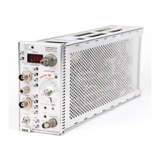
100 MHz differential comparator vertical plug-in for 7000-series scopes
Brand:
Tektronix
| Category:
Amplifier
| Size: 15 MB
Table of Contents
Table of Contents
3
Introduction
5
Electrical Characteristics
5
System Characteristics
8
Introduction
9
Front Panel Description
9
Test Setup Chart
10
Familiarization Procedure
10
General Operating Information
13
Circuit Description
17
Input Resistance & DC Attenuator Compensation Attenuation Ratio Adjustm Nts Adjustments
44
Attenuation Ratio (R8G)
54
Check/Adjust INPUT DC
54
Input Resistance & DC
54
Check/Adjust + INPUT 1X DC Input
55
Resistance (R7)
55
Attenuation Ratio (R5E)
56
Check
56
Check/Adjust
56
Check/Adjust INPUT 100X DC
56
Check/Adjust -- INPUT 1X DC Input
57
Resistance (R27)
57
Check/Adjust
58
High-Frequency
58
Both Inputs)
60
1% or ±0 .06 Division for a 6-Division Peak-To-Peak
66
Check/Adjust
66
Check/Adjust -+- INPUT Attenuator
66
100 Khz
69
20 Mhz 1V
69
Check/Adjust Attenuator Common
69
Sine-Wave
69
(Including a Trigger Gain Check)
72
Check Trigger Amplifier Gain and Step
72
Trigger and Signal Amplifier Response Checks
72
Check
73
Check
75
Check/Adjust +V C Cal (R686)
76
Check/Adjust --V C Cal (R727)
76
Check/Adjust --VC Zero (8720)
76
Check/Adjust DVM Zero (R708)
76
Check/Adjust _+VC Zero (R696)
76
Comparison Voltage Adjustments
76
Check +V C Linearity
77
Check V C out Resistance
77
Check Noise
78
Check Overdrive Recovery Time
79
Tektronix 7A13 Instruction Manual (125 pages)
DIFFERENTIAL COMPARATOR
Brand:
Tektronix
| Category:
Industrial Equipment
| Size: 62 MB
Table of Contents
Table of Contents
3
Specification
5
Introduction
5
Electrical Characteristics
5
System Characteristics
8
Environmental Characteristics
8
Operating Instructions
9
Introduction
9
Front Panel Description
9
Familiarization Procedure
10
Test Setup Chart
10
General Operating Information
13
The Following Servicing Instructions
17
Are for Use by Qualified Personnel Only
17
Circuit Description
19
Block Diagram Description
19
Detailed Circuit Description
21
Maintenance
29
Preventive Maintenance
29
Troubleshooting
30
Corrective Maintenance
36
Performance Check/Calibration
41
Test Equipment Required
41
Index and Short-Form Performance Check/Calibration Procedure
45
Performance Check/Calibration Procedure
48
Check/Adjust Position Center (R335)
50
DC and GAIN ADJUSTMENTS
50
Check/Adjust 10X DC Bal (R307)
51
Check/Adjust Position Center
51
INTERACTION-Repeatstep
51
Check Gate Current
52
Check/Adjust Gain (R329 Front Panel)
52
Check/Adjust Signal Output DC Level
52
Check/Adjust Trigger DC Balance
52
Check/Adjust Trigger Output DC Level
52
Check Comparison Voltage
54
Check/Adjust Overdrive Thermal
54
Compensation (R167)
54
Preliminary Comparison Voltage Check & Thermal Compensation Adjustment
54
Electrical Partslist
85
Parts Ordering Information
85
Diagrams Andcircuit Board Illustrations
103
Symbols and Reference Designators
103
Change Information
122
Advertisement
Tektronix 7A13 Instruction Manual (131 pages)
DIFFERENTIAL COMPARATOR
Brand:
Tektronix
| Category:
Industrial Equipment
| Size: 63 MB
Advertisement
Related Products
Tektronix 7A18A
Tektronix 7A19
Tektronix 7A18
Tektronix 7A18N
Tektronix 7a11
Tektronix 7A16P
Tektronix 7a15
Tektronix 7a15a
Tektronix 7a15an
Tektronix 7A16A
Tektronix Categories
Test Equipment
Measuring Instruments
Amplifier
Portable Generator
Printer
More Tektronix Manuals
Login
Sign In
OR
Sign in with Facebook
Sign in with Google
Upload manual
Upload from disk
Upload from URL