Sign In
Upload
Manuals
Brands
Tektronix Manuals
Tool Storage
372
Tektronix 372 Semiconductor Workbench Manuals
Manuals and User Guides for Tektronix 372 Semiconductor Workbench. We have
1
Tektronix 372 Semiconductor Workbench manual available for free PDF download: User Manual
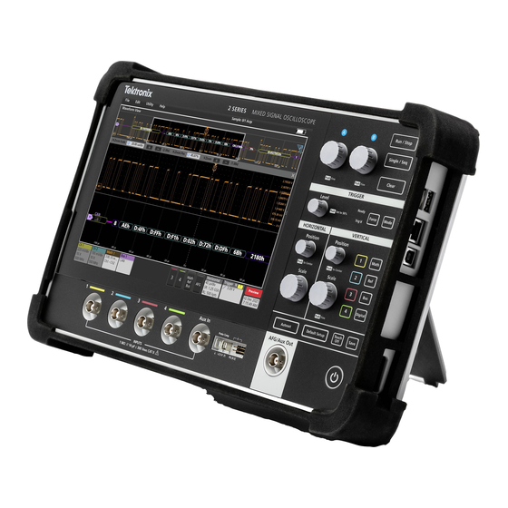
Tektronix 372 User Manual (364 pages)
Semiconductor Workbench
Brand:
Tektronix
| Category:
Tool Storage
| Size: 3 MB
Table of Contents
Table of Contents
7
Figure 1 20: SAVE Pop up Menu
18
Figure 1 30: LOAD Pop up Menu
18
Safety
23
Consignes de Sécurité
25
Getting Started
31
Overview
33
Product Description
33
Measurement Units
33
Measurement Configuration
33
Auxiliary Voltage Supply Unit
33
Test Fixture
34
Acquisition, Display and Analysis
34
User Interface
34
Floppy Disk Drive
35
372 Based Programming
35
Remote Control (GPIB)
35
Video Printer, Centronics, Plotter and TTL I/O
35
Start up
37
Safety
37
Operation
37
Figure 1 1: Location of the Line Voltage Indication
37
Figure 1 2: Optional Power Cords
38
Table 1 1: AC Voltage Ranges and Fuse
39
Figure 1 3: Connection between the 372 and the Test Fixture
40
Figure 1 4: FLOATING Terminal, GROUND Terminal and SHORTING BAR
40
Power on
41
Figure 1 5: ON/STBY Switch and Start up Menu
41
Self Test
42
Power down
42
Figure 1 6: Diagnostic Menu
42
Tutorial
43
Introduction
43
Example 1 - the Measurement Process
44
Powering up and Initialization
44
Figure 1 7: Simplified Measurement Circuit and Result of ID Vs VDS Characteristic
44
Mounting a DUT
45
Figure 1 8: Power up and Start up Menu
45
Figure 1 9: Mounting of a FET
46
Table 1 2: Connections of the DUT Leads
46
Setups
47
Configuration with CATALOG Setups
47
Averaging and Acquisition Parameters
48
Figure 1 10: Catalog Setup Menu
48
Figure 1 11: Operation Mode Setup
48
Source Setup
50
Figure 1 12: Source Setup
50
Table 1 3: Parameters in Source Setup
51
Figure 1 13: Change the Stop Value of the HPU
52
Measurement and Auto Scaling
53
Figure 1 14: Change the Measure Range of the LPU
53
Measurement Using the Cursors
54
Figure 1 15: [AUTO SCALE] Soft Button and [SINGLE] Button
54
Figure 1 16: Application Selection Box, [CURSOR TYPE] Selector, Cursor Type Pop up Menu
55
Figure 1 17: Position of Point 1 of the SLOPE Cursor
56
Figure 1 18: Position of Point 2 of the SLOPE Cursor
57
Figure 1 19: Floppy Disk Drive
58
Figure 1 21: Character Keypad Pop up Menu
59
Example 2 - Other Ways to Setup
60
Manual Setup
60
Figure 1 22: UTILITY Menu and [INITIALIZE] Soft Button
60
Connection and Source Mode
61
Figure 1 23: CONFIG Menu
61
Figure 1 24: Connection Setup and Pop up Menu
61
Measurement Mode
62
Figure 1 25: Connection Pop up Menu
62
Sweep Mode
63
Figure 1 26: Operation Mode Setup
63
Averaging and Acquisition Parameters
64
Graph Display
64
Figure 1 27: Graph Display
64
Source Setup
65
Axis Label
65
Figure 1 28: MEASURE Menu
65
Recalling Settings
66
Figure 1 29: DISK Menu and FILE/DIR List
67
Example 3 - Measurements Using the Cursor
69
Figure 1 31: Mounting the BJT
69
Figure 1 32: Mounting a DIODE
70
Figure 1 33: Major Menu and Application Selection
70
Bjt
71
Figure 1 34: Settings for IC&IB Vs. VBE
71
Figure 1 35: Application Menu, Cursor Type Pop up Menu
72
Figure 1 36: Positioning Point 1 of the SLOPE Cursor
73
Figure 1 37: Point 2 of the SLOPE Cursor and Readout
74
Fet
76
Diode
78
Example 4 - Time Domain Measurement
81
Setting up
81
Table 1 4: Example of Time Domain Measurement Setup
84
Table 1 5: X and y Axis Scale Settings
85
Measurement
86
About the Sample Disk
88
Fet
88
Bjt
88
Dio
89
Operating Basics
91
Basic Menu Operation
93
Touch Area
93
Box and Selection Box
93
Selectors
94
Soft Buttons
94
Soft Keys
94
Graphs
94
Other Areas
95
Pop up Menu
95
Selector Operation
97
Entry of Text
98
Entry of Numerals
98
Moving Objects
99
Scrolling
101
Button/Soft Button Operation
102
Mounting the Device under Test
103
Attaching the Test Adapter
103
Mounting the DUT and Wiring
104
Protective Cover
104
Basic Patch Wiring Examples
105
Table 2 1: Connections of the DUT Leads
105
Before and after Floating Measurement
109
Reference
111
At a Glance
113
Front Panel
114
Front Panel Controls
115
Rear Panel
116
Test Fixture with Test Adapters
118
Rear Panel of the Test Fixture
119
Patch Panel
120
Test Adapters
121
Main Menu
122
CONFIG Menu (Sweep Measurement Mode)
123
CONFIG Menu
123
(Time Domain Measurement Mode)
124
Catalog Setup Menu
125
Measure Menu
126
Utility Menu
127
PROG Menu (Program Trace Menu)
128
PROG Menu (Program Editing Menu)
129
Disk Menu
130
Measurement System
131
Measurement Circuit
131
Hpu/Lpu
132
Gndu
133
Matrix Switch
133
Floating Chassis
133
Test Fixture
134
Protective Cover and Interlock System
134
DUT Connection and Kelvin Sense
134
Measurement Modes and Acquisition
136
Sweep Measurement Mode
136
Time Domain Measurement Mode
139
Averaging
139
Pulse Mode
140
Measurement Data and Graph Display
142
Curve Analysis
142
Range and Resolution
144
Table 3 1: Voltage Range and Resolution of the LPU
145
Table 3 2: Current Range and Resolution of the LPU
145
Table 3 3: Voltage Range and Resolution of the HPU
145
Table 3 4: Current Range and Resolution of the HPU
145
Table 3 5: Divided Values Per 1 Decade (10)
146
Table 3 6: Divided Values Per 1 Decade (20)
146
Table 3 7: Divided Values Per Decade (40)
146
Table 3 8: Operating Range in Logarithmic Sweep Mode
147
Table 3 9: Resolution and Time Operating Range
147
Setups
149
Introduction
149
Configuration
150
Catalog Setup
150
Table 3 10: Device Type Selection
151
Table 3 11: Test Item Selection
151
Operation
153
Setup Using the CATALOG
153
Manual Setup
153
Sweep Mode
156
Table 3 12: Measurement Mode Selection
156
Table 3 13: Master Slave Selection
156
Table 3 14: Master Sweep Mode Selection
157
Table 3 15: Slave Sweep Mode Selection
157
Measurement Data and Graph Display
159
Table 3 16: X/Y Axes Data Selection
159
Averaging and Acquisition Parameters
161
Table 3 17: Averaging Mode Selection
161
Table 3 18: Sampling Interval Range
162
Source Setup
163
Measure Range, Compliance and R Mode (Protective Resistance)
163
Table 3 19: Current Range for Compliance
165
Table 3 20: Voltage Range for Compliance
165
Source Output
166
Table 3 21: Protective Resistance Selection
166
Table 3 22: Output Related Parameters to be Set in Source Setup
167
Table 3 23: Increment_Log Selection
168
Axis Label
170
Pulse Mode
171
Introduction
171
Switching Pulse Mode
172
Supplied Channel
172
Pulse Parameters
172
Table 3 24: Channel Selection
172
Table 3 25: Trigger Source Selection
172
Auxiliary Voltage Supply
175
Setup
175
Measurement
177
Single Measurement
177
Repeated Measurement
178
Dynamic Changes of Settings
178
Adjusting the Graph Display
181
Introduction
181
Automatic Scaling Adjustment
182
Manual Scaling Adjustment
182
Y Axis (Vertical Axis)
182
Y Axis Range
183
Axis (Horizontal Axis)
184
Axis Range
185
Mathematical Operation
187
Introduction
187
Operation
187
Algorithm
188
Table 3 26: Equation Selection
188
Switching Graph Display
191
Table 3 27: Display Source Selection
192
Parameter Analysis Using the Cursor
193
Introduction
193
Operation
193
Selecting Cursor and Cursor Type
194
Moving Cursor
194
Table 3 28: Cursor Type Selection
194
Cursor Types
196
Table 3 29: Interpolate Selection
196
Table 3 30: DOT Cursor Readout
197
Table 3 31: SLOPE Cursor Readout
198
Table 3 32: SLOPE Cursor Move Selection
200
Table 3 33: XGONOGO Cursor Readout
201
Table 3 34: XGONOGO Cursor Move Selection
202
Table 3 35: YGONOGO Cursor Readout
204
Zoom
207
Setup
207
Zoom Area
208
Zoom in
208
Reset Zoom
208
Text Editing on the Graph
211
Introduction
211
Creating a Label
212
Moving the Label
214
Removing the Label
215
Renaming the Label
215
Erasing Labels
216
Save and Load Settings, Curves and Programs
219
Introduction
219
Save Settings, Curves and Programs
219
Load Settings, Curves and Programs
221
Hardcopy
223
Introduction
223
Installation
223
Epson Printer
223
HPGL Plotter
223
Video Printer
225
Floppy Disk
225
Operation
225
Initializing the 372
229
Date and Time
231
Time Stamp
233
Adjusting CRT Brightness
235
ID Information
237
Floppy Disk System
239
Introduction
239
Directories, Files and Path
239
File Name
240
Reference of Files and Directories
240
Operation
241
Floppy Disk Handling Precautions
241
File Protection
241
Inserting a Floppy Disk
242
Removing a Floppy Disk
243
DISK Menu Overview
243
Outline of File Operations
245
Saving Settings, Curves and Programs
246
Loading Settings, Curves and Programs
247
Creating a New Directory
248
Changing Current Working Directory
248
Copying a File
249
Removing a File/Directory
250
Renaming File/Directory
251
Formatting a Floppy Disk
251
372 Based Programming
255
Overview of Features
255
Instructions
255
Program Editing
255
Trace Feature
255
Single Step Mode
256
Continuous Mode
256
Controlling/Interrupting Another Instrument
256
PROG Menu Overview
256
Menu Selection
257
Editing a Program
257
Controlling Program List Displays
258
Entering a Program
258
Modifying Programs
259
Program Execution
262
Execution in Normal Mode
263
Execution in Trace Mode
263
Saving and Loading the Program
265
Programming
265
Program Structure
265
Flow Control
266
Register
267
Instruction Set
267
Sample Programs
273
Example 1
273
Example 2
275
Example 3
276
Example 3 1: PRG_BJT3.PRG
276
Example 3 2: PRG_BJT4.PRG
277
Example 4
278
Gpib
281
Connector and Cable
281
Configurations
282
Types of Devices
282
Restrictions
283
Functional Elements
283
GPIB Parameters
284
Device Addresses
284
Primary Address
284
Listen Address
284
Talk Address
285
Interface Messages
285
Appendices
287
Appendix A: Options and Accessories
289
Power Cord Options
289
OPTION 20: Extension Cable Set
289
OPTION 1R: Rackmounting
289
Standard Accessories
290
Other Accessories
291
Appendix B: Specifications
293
Recommended Calibration Schedule
293
Nominal Traits
293
Electrical Specification
293
Test Fixture Specification
298
Warranted Characteristics
299
Typical Characteristics
307
Appendix C: Calibration and Diagnostics
313
Calibration and Reference Voltage Adjustment
313
Self Diagnostics
313
Operation
314
Adjusting the Reference Voltage
314
Calibration
317
Self Test
319
Check of Front Panel Control and TTL I/O
333
Appendix D: Factory Initialization Settings
339
ID Vs. VDS
340
IDSS Vs. VDS
341
IGSS Vs. VGS
342
ID Vs. VGS
343
Gm Vs. VGS
344
Gm Vs. ID
345
IC Vs. VCE
346
ICBO Vs. VCBO
347
IEBO Vs. VEBO
348
BETA Vs. IC
349
VCE & VBE Vs. IC
350
IC Vs. VBE
351
IC Vs. IB
352
IC & IB Vs. VBE
353
IB Vs. VCE
354
IF Vs. VF
355
IR Vs. VR
356
Appendix E: Messages
357
Appendix F: Connector Pin Assignment
359
TTL I/O Interface
359
Video Printer Interface
360
Test Fixture Interface
361
Appendix G: Repackaging for Shipment
363
Advertisement
Advertisement
Related Products
Tektronix KEITHLEY 3724
Tektronix KEITHLEY 3723
Tektronix KEITHLEY 3720
Tektronix KEITHLEY 3722
Tektronix Keithley 3721
Tektronix Keithley 3721 ST
Tektronix Keithley 3721 MTC 15
Tektronix 371B
Tektronix Keithley 3706A
Tektronix KEITHLEY 3731
Tektronix Categories
Test Equipment
Measuring Instruments
Amplifier
Portable Generator
Printer
More Tektronix Manuals
Login
Sign In
OR
Sign in with Facebook
Sign in with Google
Upload manual
Upload from disk
Upload from URL