Sign In
Upload
Manuals
Brands
Tektronix Manuals
Measuring Instruments
1720
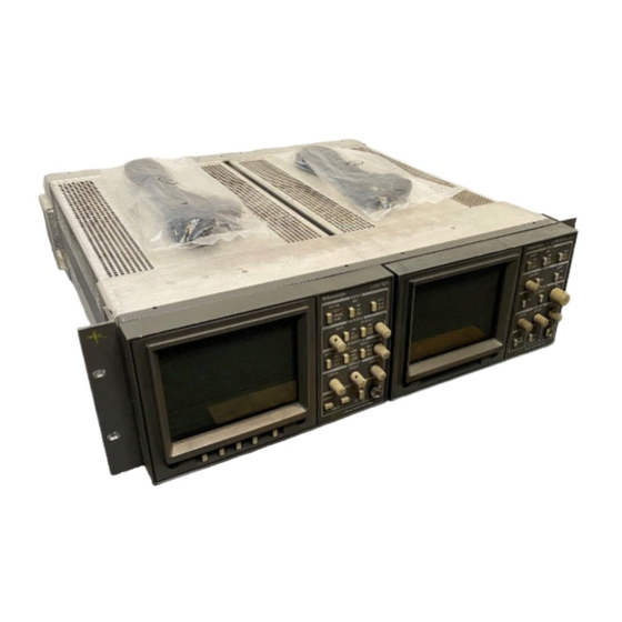
Tektronix 1720 Manuals
Manuals and User Guides for Tektronix 1720. We have
2
Tektronix 1720 manuals available for free PDF download: Instruction Manual
Tektronix 1720 Instruction Manual (226 pages)
Vectorscope
Brand:
Tektronix
| Category:
Measuring Instruments
| Size: 2 MB
Table of Contents
Table of Contents
5
General Safety Summary
12
Preface
14
Section 1 Introduction and Specification
17
Accessories
20
Standard Accessories
20
Optional Accessories
20
Options
20
CRT Options
20
Power Cord Options
20
Safety Information
21
Specifications
21
Table 1-1: Signal Input
22
Table 1-2: Vector Mode
22
Table 1-3: XY Mode
24
Table 1-4: CRT Display
24
Table 1-5: Power Source
24
Table 1-6: Environmental Characteristics
25
Section 2 Operating Instructions
27
Front-Panel Controls and Indicators
29
Figure 2-1: Control and Indicator Locations
29
Gain
30
Input
30
Display
31
Miscellaneous
31
Phase
31
Rear-Panel Connectors
32
Figure 2-2: 1720/1721 Rear Panel
33
Using the 1720/1721 in Auxiliary Mode
34
INPUT Switching
34
REF Switching
35
Line Select
35
Store
35
Recall
35
Figure 2-3: Signal Connection for the Operator's Checkout Procedure
37
Figure 2-4: 1720/1721 Typical Vector Display
38
Figure 2-5: Modulated Staircase Waveform Shown on a 1721
39
Figure 2-6: Color Bar and Modulated Staircase Signals both Displayed on a 1721
40
Figure 2-7: Connection for Using Black Burst Signal for External Reference
41
Figure 2-8: 1720/1721 Test Circle Display
42
Measurement Applications
43
Color Measurements
44
Figure 2-9: NTSC Standard Color Phase Vector Diagram
44
Figure 2-10: PAL Standard Color Phase Vector Diagram
45
Figure 2-11: Partial 1720 Graticule Showing the 75% Amplitude Burst Target
46
Figure 2-12: Partial 1721 Graticule Showing the 75% Amplitude Burst Target
46
Functional Use of the Vector Graticule
47
Measurement of Color Bars
47
Figure 2-13: Fine Detail of the 1720 Graticule Magenta Target
48
Figure 2-14: Fine Detail of the 1721 Graticule Target
49
Figure 2-15: Simulated 1720 Graticule Showing the Relationship between Amplitudes on the
49
Differential Gain and Phase Measurements
50
Figure 2-16: Simulation of a 1721 Graticule Showing the Relationship between Amplitudes
50
Figure 2-17: a Simulation of a Part of the 1720 Graticule Showing the Differential Phase and
51
Y Measurements
52
Making Stereo Audio Phase Measurements
52
Figure 2-18: Simulation of the 1721 Differential Gain and Phase Graticule Showing
52
Looking at Incidental Carrier Phase Modulation
53
Service Safety Summary
57
Section 3 Installation
59
Packaging
61
Electrical Installation
61
Power Source
61
Mains Frequency and Voltage Ranges
61
Operating Options
61
Y INPUT Connector
61
Figure 3-1: Plug Jumper Locations
62
Table 3-1: Internal Jumper Selection
62
Auxiliary Connector
63
Mechanical Installation
64
Cabinetizing
64
Table 3-2: AUXILIARY Connector Pin Assignments
64
Figure 3-4: 1700F00 Plain Cabinet
65
Securing the Instrument in Its Cabinet
66
Figure 3-5: 1700F02 Portable Cabinet
66
Rack Mounting
67
Figure 3-6: Cabinet Securing Screws
67
Figure 3-7: 1700F05 Rack Adapter
67
Figure 3-8: 1700F05 Rack Adapter Adjustment
68
Figure 3-9: 1720/1721 and 1700F06 Blank Panel
68
Custom Installation
69
Figure 3-10: Typical Custom Installation Showing the Console
69
Section 4 Theory of Operation
71
Overview
73
Block Diagram
74
Video Input
74
Luminance Processing
74
Microprocessor
74
Section 4 Theory of Operation
75
Gain Cell
75
Chrominance Processing
75
Figure 4-1: Simple Block Diagram of a 1720/1721 Vectorscope
75
Demodulators
76
Output Amplifiers
76
CRT Blanking
76
Circuit Descriptions
77
Diagram 1 Input and Deflection Amplifiers
77
Video Input Amplifiers
77
Gain Cell
78
Diagram 2 Subcarrier Regenerator
78
Reference Switch
79
Sync Separator
80
Bowes Oscillator
80
Back Porch Sample
80
Loop Phase Detector and Amplifier
80
Luminance and Chrominance Amplifiers
80
Quadrature Phase Detector and Amplifier
81
Burst Clamp
81
Lock Detector and Bandwidth Switch
81
Error Amplifier
81
PAL Phasing
82
Vcxo
82
Diagram 3 Demodulator
83
V-Axis Switcher
83
Chrominance Demodulators
84
Sync Tip Chrominance Clamp
84
Demodulator Output Filters and Amplifiers
84
Vector Center Dot Position Clamp
84
Diagram 4 Deflection Amplifier
85
XY Input Amps
86
Deflection Amplifiers
86
Center Dot Comparators
86
CRT Blanking
86
Diagram 5 Microprocessor
87
Microprocessor
87
Table 4-1: U613 Switching Control Outputs
88
Diagram 6 Control Circuit
89
Z-Axis Control
89
Trace Rotation
90
Graticule Illumination
90
Post Regulators
90
Diagram 7 Low Voltage Power Supply
91
Output Filters
92
Error Amplifier
93
Feedback Transformer Driver and Peak Detector
93
Output HV Shutdown
93
Diagram 8 High Voltage Power Supply
94
Focus Amplifier
95
Grid Drive Circuit
95
Z-Axis Amplifier
95
Section 5 Checks and Adjustments
97
Recommended Equipment List
99
Electrical Instruments
99
Section 5 Checks and Adjustments
100
Auxiliary Equipment
101
Performance Check Procedure Short-Form Reference
103
Table 5-1: Performance Check Procedure Short-Form Reference
103
Performance Check Procedure
104
Figure 5-2: Loop–Through Connection of Black Burst Signal to both EXT REF and CH-B
105
Figure 5-3: Using the Vector Graticule –3 Db Markings to Measure Bandwidth
106
Figure 5-4: Signal Connection for Checking CH-A/CH-B Phase Matching
108
Figure 5-5: Rear-Panel XY INPUT Connector Showing Inputs
112
Figure 5-6: Audio Frequency XY Display
113
Adjustment Procedure
115
Signal Connections
115
Adjustment Procedure Short-Form Reference
116
Figure 5-8: Starting Connections for the Adjustment Procedure
116
Table 5-2: Adjustment Procedure Short-Form Reference
117
Long-Form Adjustment Procedure
118
Figure 5-9: Test Points and Adjustment Locations for the 11.8V Supplies
119
Section 6 Maintenance
125
Preventive Maintenance
127
Cleaning
127
Visual Inspection
128
Table 6-1: Static Susceptibility
128
Performance Checks and Readjustments
129
Troubleshooting
130
Foldout Pages
130
Parts Lists
131
Major Assembly Interconnection
131
Specific Troubleshooting Procedures
134
Power Supply
134
Introduction
134
Low Volts Supply
135
High Volts Supply
135
Table 6-2: Power Supply Fault Symptoms
135
Table 6-3: Low Volts Supply Voltages
135
Table 6-4: Control Circuit Test Points
137
High Volts Supply
138
Table 6-5: High Volts Supply Fault Symptoms
138
Table 6-6: High Voltage Oscillator Test Points
139
Serial Port and LED Driver Diagnostics
140
Corrective Maintenance
141
Mechanical Disassembly/Assembly
142
Bezel Removal
142
Graticule Light Removal and Replacement
143
CRT Removal
144
Replacement of the CRT
144
Removing the Rear Panel
145
Removing the Front Panel Circuit Board
146
Removing the Main Board
147
Removing the Power Supply Board
148
Repackaging
149
Identification Tag
149
Repackaging for Shipment
149
Figure 6-8: Repackaging
150
Section 7 Options
151
Options
153
Power Cord Options
153
Field Upgrade Kits
153
Cabinets
153
Plain Cabinet (1700F00)
154
Carrying Case (1700F02)
154
Side-By-Side Rack Adapter (1700F05)
154
Ordering
154
Section 8 Replaceable Electrical Parts
155
Parts Ordering Information
157
Using the Replaceable Electrical Parts List
157
Section 8 Replaceable Electrical Parts
163
Section 9 Diagrams/Circuit Board Illustrations
189
Section 10 Replaceable Mechanical Parts
213
Section 10 Replaceable Mechanical Parts
218
Advertisement
Tektronix 1720 Instruction Manual (138 pages)
VECTORSCOPE
Brand:
Tektronix
| Category:
Test Equipment
| Size: 10 MB
Table of Contents
Change Information
2
Table of Contents
6
List of Tables
10
Operator's Safety Summary
13
1720-Series
13
Service Safety Summary
14
For Qualified Service Personnel Only
14
Section 1 Introduction
16
Standard Accessories
16
Optional Accessories
17
Field-Installable Upgrades
17
L * Power Cord Options
17
Safety Information
17
Specification
17
Supplemental Information
18
Section 2 Operating Instructions
24
Front-Panel Controls and Indicators
24
Input 2.0
24
Fig. 2-1 Control and Indicator Locations
25
Miscellaneous
26
Subminiature D-Type Connectors
28
Power Input
28
Miscellaneous
28
INPUT Switching
28
REF Switching
28
Line Select 2.10
28
Operator's Checkout Procedure
29
Fig. 2-4 1720-Series Typical Vector Display
30
Fig. 2-7 Connection for Using Black Burst Signal for External Reference
31
Fig. 2-8 1720-Series Test Circle Display
31
Measurement Applications
32
Color Measurements
32
Fig. 2-9 NTSC Standard Color Phase Vector Diagram
33
Fig. 2-12 1721 Graticule Showing the Fig. 2-13 Fine Detail of the Magenta Targets of the 1720 Graticule
34
Measurement of Color Bars
35
Fig.2-14
36
Fig. 2-15 1720 Graticule Showing Relationship between the Vector Targets and the
36
Differential Gain and Phase Measurements
37
Fig. 2-16 1721 Graticule Showing Relationship between the Vector Targets and the U and V Modulation Axes
37
Fig.2-18 | Makingdifferential Gain Measurements
38
Y Measurements
39
Making Stereo Audio Phase Measurements
39
Looking at Incidental Carrier Phase Modulation
39
Service Information
41
Packaging
41
Electrical Installation
41
Power Source 2.0.0.0
41
Mains Frequency and Voltage Ranges
41
Section 3 Installation
41
Operating Options
41
Auxiliary Control
42
YINPUT Connector
45
AUXILIARY Connector
45
Mechanical Installation
45
Rackmounting
45
Custom Installation 0.0.0.0
46
Fig. 3-6 1700F
46
Cabinet Options ©0000
47
DC Power Supply Field Upgrade
47
Fig. 3-7 a Typical Console Installation that Can be Used as a Guide When Customizing
47
Rear View
48
Side View
48
Bottom View
48
Section 4 Theory of Operation
49
Block Diagram
49
Fig. 4-1 Block Diagram of the 1720-Series
50
Videoinput
51
Chrominance Processing
51
Output Amplifiers
52
Circuit Descriptions
52
Xyinputamps
53
Deflection Amplifiers
53
Center Dot Comparators
53
Reference Switch
54
Reference AMPS
54
Sync Separator
54
} Fig. 4-2. Block Diagram of the Phase Lock Loop
54
Back Porchsample
55
Burstclamp
55
Lock Detector and Bandwidth Switch
55
Error Amplifier 2.00.0
55
PAL Phasing
56
VCXO and Phase Shifter
56
Low-Voltage Power Supply
59
Checks and Adjustments
62
Recommended Equipment List
62
Performance Check
64
Performance Check Procedure
65
Preliminary Setup
65
Fig. 5-2 Loop-Through Connection of Black Burst Signal to both EXT REF Andch-B
65
Ref Input
68
Fig. 5-5 Connections for Variable Gain Check
69
Fig. 5-6 Setting up the Return Loss Bridge
70
Fig. 5-8 Rear-Panel XY INPUT Connector Showing Inputs
71
Fig. 5-9 Audio Frequency XY Display
71
Main Board
73
Fig. 5-11 Starting Connections for the Adjustment Procedure
74
Section 6 Maintenance
77
Preventive Maintenance
77
Visual Inspection
77
Static-Sensitive Components
78
Troubleshooting
78
Parts Lists 2.20
80
Major Assembly Interconnection
81
General Troubleshooting Techniques
81
Serial Port and LED Driver Diagnostics
82
Obtaining Replacement Parts
82
Mechanical Disassembly/Assembly
83
CRT Removal
83
Removing the Rear Panel
85
Removing the Front Panel Circuit Board
85
Removing the Main Board
85
Removing the Power Supply Board
86
Front Panel Assembly
86
Identification Tag
86
Repackaging for Shipment
87
Section 7 Options
89
Cabinets
89
Plain Cabinet (1700F00)
89
Side-By-Side Rack Adapter (1700F05)
89
DC Power Supply
89
DC Power Supply Field Upgrade Kit (1700F10)
89
Battery Pack (BP1) 20.0
90
Section 8 Replaceable Electrical Parts
91
Parts Ordering Information
91
Cross Index-Mfr. Code Number to Manufacturer
91
Section 9 Diagrams and Circuit Board Illustrations
118
Replaceable Mechanical Parts
132
Indentation System
132
Fig.2-17
136
Advertisement
Related Products
Tektronix 1721
Tektronix 1710J Series
Tektronix 1401A
Tektronix 1L20
Tektronix 1502
Tektronix 1L10
Tektronix 1L30
Tektronix 1502B
Tektronix 1340
Tektronix 1L60
Tektronix Categories
Test Equipment
Measuring Instruments
Amplifier
Portable Generator
Printer
More Tektronix Manuals
Login
Sign In
OR
Sign in with Facebook
Sign in with Google
Upload manual
Upload from disk
Upload from URL