Sign In
Upload
Manuals
Brands
TECO Manuals
Inverter
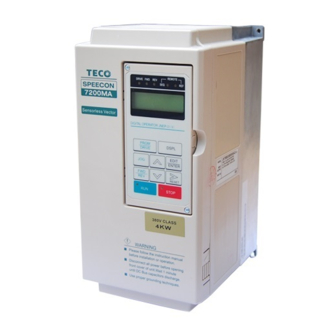
speecon 7200ma
TECO speecon 7200ma Manuals
Manuals and User Guides for TECO speecon 7200ma. We have
1
TECO speecon 7200ma manual available for free PDF download: Instruction Manual
TECO speecon 7200ma Instruction Manual (129 pages)
Brand:
TECO
| Category:
Inverter
| Size: 2 MB
Table of Contents
Note for Safe Operation
2
Table of Contents
4
7200 MA Handling Description
5
Inspection Procedure Upon Receiving
5
Inverter Nameplate
5
Inverter Model Number
5
Installation
6
Removing/Attaching the Digital Operator and Front Cover
7
Removing the Digital Operator
7
Mounting the Front Cover and Digital Operator
7
Removing the Front Cover
8
Wiring between Inverter and Peripheral Devices and Notice
9
Example of Connection between the 7200MA and Typical Peripheral Devices
10
2-A Standard Connection Diagram
11
2-B Standard Connection Diagram
12
2-C Standard Connection Diagram
13
Description of Terminal Function
14
Main Circuit Terminals Table
14
Terminal Block Configuration
14
Control Circuit Terminals Table
15
Wiring Main Circuit and Notice
17
220V and 440V Class Applicable Wire Size and Connector
17
External Circuit Wiring Precaution
18
Grounding
19
7200MA Ground Winding Diagram
19
Inverter Specifications
20
Dimensions
22
Peripheral Units
24
Braking Resistors
24
AC Reactor
25
Input Side Noise Filter
26
EMI Suppression Zero Phase Core
27
LCD Operator with Extension Wire
28
The Physical Dimension of LCD Digital Operator
28
Analog Operator
29
PROFIBUS Communication Card
29
2 Using LCD Digital Operator
30
Key's Functions
31
3 Operating Status Diagram
31
Display Contents in DRIVE Mode and PRGM Mode
32
Parameter Description
33
Example of Using LCD Digital Operator
34
Operation Mode
34
Example of Operation
34
Example of Display (Use ˄ and ˅ Keys to Display Monitored Items/Contents)
36
3 Parameter Setting
37
Frequency Command (in Multi-Speed Operation)
37
Parameters Groups Can be Changed During Running Bn-
38
Set Individual Acceleration/Deceleration Times
40
Analog Input Gain and Bias Diagram
41
Auto Torque Boost Gain (Bn-11)
41
Monitor 1 (Bn-12)
42
Monitor 2 (Bn-13)
42
Multi-Function Analog Output AO1 Gain (Bn-14)
43
Multi-Function Analog Output AO1 Gain (Bn-15)
43
Block Diagram for PID Control in Inverter
43
Response of PID Control for STEP-Shape (Deviation) Input
44
Time Setting in Auto_Run Mode (Bn-21∼Bn-36)
44
Timer On_Delay Time (Bn-37)
45
Timer Off_Delay Time (Bn-38)
45
An Operation Example of Timer Function
45
Time Chart for Energy-Saving Operation
45
Control Parameters Cn-
46
Input Voltage Setting (Cn-01)
49
V/F Curve Parameter Settings (Cn-02∼Cn-08)
49
User-Defined V/F Curve
49
Motor Rated Current (Cn-09)
49
Motor No-Load Current (Cn-10)
50
Output Frequency with Slip Compensation
50
Motor Rated Slip (Cn-11)
50
Slip Compensation Limit
50
Motor Line-To-Line Resistance (Cn-12)
51
Motor Iron-Core Loss (Cn-13)
51
DC Injection Braking Time at Stop (Cn-16)
51
DC Injection Braking Time at Start (Cn-17)
51
DC Injection Braking Time Chart
52
Frequency Command Upper Bound (Cn-18)
52
Frequency Command Lower Bound (Cn-19)
52
Upper and Lower Bounds of the Frequency Command
52
Setting Jump Frequencies
53
Number of Auto Restart Attempt (Cn-24)
53
Stall Prevention Level During Acceleration (Cn-25)
54
Stall Prevention Level During Running (Cn-26)
54
Acceleration Stall Prevention Function
54
Run Stall Prevention Function
54
LCD Digital Operator Display Unit (Cn-28)
55
Frequency Agree Detection Level During Acceleration (Cn-29)
56
Frequency Agree Detection Level During Deceleration (Cn-30)
56
Frequency Agree Detection Width (Cn-31)
56
Overtorque Detection Level (Cn-32)
57
Overtorque Detection Time (Cn-33)
57
Time Chart for Overtorque Detection
57
Carrier Frequency Setting (Cn-34)
57
Speed Search Timing Chart
58
Speed Search Detection Level (Cn-35)
58
Speed Search Time (Cn-36)
58
Min. Baseblock Time (Cn-37)
58
Low Voltage Alarm Detection Level (Cn-39)
60
Slip Compensation Primary Delay Time (Cn-40)
60
Using the S-Curve Characteristic Function for Acceleration and Deceleration
60
S Curve Chart
60
PG Parameter (Cn-45)
61
Pole Number of Motor (Cn-46)
61
Excessive Speed Deviation Detection Level (Cn-53)
61
Overspeed Detection Level (Cn-54)
61
PID Integral Upper Bound (Cn-55)
62
PID Primary Delay Time Constant (Cn-56)
62
Motor Line-To-Line Resistance R1 (Cn-57)
62
Motor Rotor Equivalent Resistance R2 (Cn-58)
62
Motor Mutual Inductance Lm (Cn-60)
63
Slip Compensation Gain (Cn-61)
63
System Parameters Sn-
64
Inverter Capacity Selection (Sn-01)
70
V/F Curve Selection (Sn-02)
71
V/F Curve of 1~2 HP Compact Size, 220V Class MA Inverter
72
V/F Curve of 3~20 HP, 220V Class MA Inverter
73
Operator Display (Sn-03)
74
Run Source Selection (Sn-04)
74
Frequency Command Setting Method Selection (Sn-05)
74
Stopping Method Selection (Sn-06)
74
Deceleration to Stop Diagram
75
Coast to Stop Diagram
75
Whole Range DC Injecting Braking Stop Diagram
75
Coast to Stop with Timer
76
Priority of Stopping (Sn-07)
76
Prohibition of REV Run (Sn-08)
76
Output Frequency UP/DOWN Function (Sn-09)
76
Frequency Command Characteristics Selection (Sn-10)
77
Scan Time at Input Terminal (Sn-11)
77
Overtorque Detection Selection (Sn-12)
77
Output Voltage Limitation Selection (Sn-13)
77
Stall Prevention Selection During Acceleration (Sn-14)
78
Stall Prevention Selection During Running (Sn-16)
78
Operation Selection at Fault Contact During Fault Retrying (Sn-17)
78
Operation Selection at Power Loss (Sn-18)
79
Zero Speed Braking Selection (Sn-19)
79
External Fault Contact Contact Selection (Sn-20)
79
Detection Mode Selection of External Fault (Sn-22)
79
Motor Overload Protection Selection (Sn-23)
80
Motor Overload Protection Curve (Cn-09 Setting = 100%)
80
Frequency Characteristics Command Selection at External Analog Input Terminal (Sn-24)
80
Multi-Function Input Setting
81
Multi-Function Input Terminal Function Selection (Sn-25)
81
Multi-Function Input Terminal Function Selection (Sn-26)
81
Multi-Function Input Terminal Function Selection (Sn-28)
81
Forward/Reverse Change (Setting:00)
82
3-Wire Mode Connection Diagram
82
Operation Sequence in 3-Wire Mode
82
2-Wire Mode Connection Diagram
82
Time Chart for Multi-Step Speed and Jog Command
83
Multi-Step Speed Command 1 - 5
83
Og Frequency Selection (Setting:06)
83
Acceleration Time and Deceleration Time Change (Setting:07)
84
External Baseblock (a Contact) (Setting:08)
84
External Baseblock (B Contact) (Setting:09)
84
Acceleration and Deceleration Ramp Hold (Setting:10)
84
Inverter Overheat Alarm(Setting:11)
85
FJOG Command (Setting:12)
85
RJOG Command (Setting:13)
85
External Fault Contact B (Setting:17)
85
Multi-Function Analog Input Setting (Setting:18)
86
Timer Function Input Terminal (Setting:19)
86
DC Injection Braking Command (Setting:20)
86
Time Chart for DC Injection Braking Command
86
LOCAL/REMOTE Control I (Setting:23)
87
LOCAL/REMOTE Control II (Setting:24)
87
RS-485 Communication Application (Setting : 25)
87
PG-Less Speed Control Action (Setting : 26)
87
Frequency UP/DOWN Function (Setting:28)
88
Time Chart of Output Frequency with the UP/DOWN Function
88
Forced Run (Setting:29)
88
Multi-Function Analog Input Function Selection (Sn-29)
89
Multi-Function Analog Input Characteristics
90
Multi-Function Output Terminal (RA-RB-RC or R1A-R1B-R1C) Function Selection (Sn-30)
91
Multi-Function Output Terminal (DO1-DOG) Function Selection (Sn-31)
91
Multi-Function Output Terminal (DO2-DOG or R2A-R2C) Function Selection (Sn-32)
91
During Running (Setting:00)
92
Zero Speed (Setting:01)
92
Run Command Mode (Setting:09)
92
Frequency Command Mode (Setting:10)
92
Overtorque Detected (Setting:11)
93
Pulse Signal Output (Setting:14)
93
Inverter Overheat (Setting:16)
93
Motor Overload (Setting:17)
93
Fault Retry (Setting:19)
94
RS-485 Communication Fault (Setting:20)
94
Timer Function Output (Setting:21)
94
RS-485 Communication Application (Setting: 22)
94
Multi-Function Analog Output (Terminal AO1) Selection (Sn-33)
95
Multi-Function Analog Output (Terminal AO2) Selection (Sn-34)
95
Pulse Output Multiplication-Gain Selection (Sn-35)
95
Different Settings of Sn-35 and Their Corresponding Multiple Numbers
95
Inverter Station Address (Sn-36)
96
RS-485 Communication Baud Rate Setting (Sn-37)
96
RS-485 Communication Parity Setting (Sn-38)
96
RS-485 Stopping Method after Communication Error (Sn-39)
96
PG Speed Control Settings (Sn-40)
97
Operation Selection at PG Opens (Sn-41)
97
Operation Selection at PG Speed Deviation over (Sn-42)
97
Overspeed Detection (Sn-43)
97
Auto_Run Mode Selection (Sn-44)
98
Auto_Run Mode Setting Selection (Sn-45~Sn-60)
98
Periodic Running (Sn-44=2, 5)
98
Auto_Run Mode for Single Cycle
99
Applied Torque Load (Sn-61)
99
LCD Language Displayed Selection (Sn-62)
100
Parameter Copy (Sn-63)
100
Ыteps to Implement the Action of Parameter Copy Betweendifferent Inverters
100
PID Function Selection (Sn-64)
100
Braking Resistor Protection Selection (Sn-65)
101
Motor Parameter Autotuning Selection (Sn-66)
101
Control Mode Selection (Sn-67)
101
Sensorless Control
101
Monitoring Parameters Un-
102
Frequency Command(Un-01)
104
Output Frequency(Un-02)
104
External Analog Command VIN (Un-06)
104
PG Speed Feedback and PG Speed Compensation (Un-13, Un-14)
104
PID Control Input (Un-15)
105
The Output Terminal Status While Last Fault Occurred (Un-29)
105
The Cumulative Time Whenever the Input Power Is on (Un-30)
105
Motor Speed While PG Feedback Is Set. (Un-33)
105
4 Fault Display and Troubleshooting
106
General
106
Error Message and Troubleshooting
107
Protective Function
107
Warning and Self-Diagnosis Functions
109
Appendix
111
Adjusting PID Controller
111
PID Control Block Diagram
113
PID Wiring Diagram
113
Supplementary on PID Control Block Diagram
113
Wiring for PG Feedback Use
114
D. RS-485 Communication Interface
115
Wiring for MODBUS Protocol Communication
115
PROFIBUS Protocol Communication
116
Wiring for PROFIBUS Protocol Communication
116
SINK/SOURCE Typical Connection Diagram
117
RS-232C Serial Communications Connection Diagram
118
Set-Up Using the Sensorless Vector Control
119
The Sequence of Motor Parameter Autotuning
119
The Operations and Adjustments of Sensorless Vector Control
120
Circuit Protection
121
Environmental Ratings
121
Field Wiring Terminals and Tightening Torque
121
Notes for Circuit Protection and Environment Ratings
121
220V Class
122
440V Class
122
Spare Parts
123
Electrical Ratings for Contstant Torque and Quadratic Torque
127
Inverter Heat Loss
128
Advertisement
Advertisement
Related Products
TECO 7200 MA Series
TECO SPEECON 7200GS
TECO 7300EV
TECO JNTMBG 7R50JK Series
TECO JNTMBG 7R50AZ Series
TECO SPEECON GS510
TECO 7300CV
TECO A510
TECO A510-2001-H
TECO A510-2001-S Series
TECO Categories
Inverter
Air Conditioner
Refrigerator
Chiller
Controller
More TECO Manuals
Login
Sign In
OR
Sign in with Facebook
Sign in with Google
Upload manual
Upload from disk
Upload from URL