TDK-Lambda Z36-12 Manuals
Manuals and User Guides for TDK-Lambda Z36-12. We have 2 TDK-Lambda Z36-12 manuals available for free PDF download: User Manual
TDK-Lambda Z36-12 User Manual (138 pages)
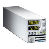
Z+ Series Programmable DC Power Supplies 200W/400W/600W/800W in 2U Built-in USB, RS-232 & RS-485 Interface Optional Interface: LXI Compliant LAN IEEE488.2 SCPI (GPIB) Multi-Drop Isolated Analog Programming
Brand: TDK-Lambda
|
Category: Power Supply
|
Size: 12 MB
Table of Contents
-
-
Introduction16
-
Accessories18
-
General18
-
AC Cables18
-
-
General30
-
General32
-
OVP Check33
-
UVL Check33
-
Load Wiring34
-
Sense Wiring40
-
-
-
Introduction42
-
Introduction49
-
Introduction50
-
Introduction51
-
-
-
Introduction52
-
Introduction54
-
Introduction59
-
CV/CC Signal66
-
Reset67
-
Save <168
-
Recall <168
-
-
-
Introduction74
-
Data Format79
-
Checksum79
-
Acknowledge79
-
Backspace79
-
Data Format86
-
Checksum87
-
Header87
-
Data Formats88
-
LIST Subsystem103
-
Status Subsystem105
-
System Subsystem107
-
WAVE Subsystem110
-
Global Subsystem112
-
-
-
Introduction113
-
FIX Mode113
-
LIST Mode114
-
WAVE Mode115
-
Trigger116
-
Input Trigger116
-
Output Trigger116
-
Wave Programing116
-
List Example117
-
Waveform Example117
-
-
-
General119
-
Fault Register120
-
Event Registers121
-
Enable Register121
-
Service Rrequest121
-
Status Register121
-
Output Queue124
-
Error Messages124
-
-
-
Introduction126
-
Specifications126
-
-
-
Introduction129
-
Troubleshooting129
-
Fuse Rating130
-
Advertisement
TDK-Lambda Z36-12 User Manual (130 pages)
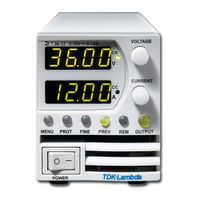
Z+ Series Programmable DC Power Supplies
Brand: TDK-Lambda
|
Category: Power Supply
|
Size: 8 MB
Table of Contents
-
-
Introduction16
-
Accessories18
-
General18
-
AC Cables18
-
-
General26
-
General28
-
OVP Check29
-
UVL Check29
-
Load Wiring30
-
Sense Wiring36
-
-
-
Introduction38
-
Introduction45
-
Introduction46
-
Introduction47
-
-
-
Introduction48
-
Introduction50
-
Introduction55
-
CV/CC Signal62
-
Reset63
-
Save64
-
Recall64
-
-
-
Introduction70
-
Data Format75
-
Checksum75
-
Acknowledge75
-
Backspace75
-
Data Format82
-
Checksum83
-
Header83
-
Data Formats84
-
Status Subsystem101
-
System Subsystem103
-
WAVE Subsystem106
-
Global Subsystem108
-
-
-
Introduction109
-
FIX Mode109
-
LIST Mode110
-
WAVE Mode111
-
Trigger112
-
Input Trigger112
-
Output Trigger112
-
Wave Programing112
-
List Example113
-
Waveform Example113
-
-
-
General115
-
Fault Register116
-
Status Register117
-
Event Registers117
-
Enable Register117
-
Service Rrequest117
-
Output Queue120
-
Error Messages120
-
-
-
Introduction122
-
Specifications122
-
-
-
Introduction125
-
Troubleshooting125
-
Fuse Rating126
-