Sign In
Upload
Manuals
Brands
SZGH Manuals
Control Systems
SZGH-CNC1000MDb Series
SZGH SZGH-CNC1000MDb Series Controller Manuals
Manuals and User Guides for SZGH SZGH-CNC1000MDb Series Controller. We have
1
SZGH SZGH-CNC1000MDb Series Controller manual available for free PDF download: User Manual
SZGH SZGH-CNC1000MDb Series User Manual (223 pages)
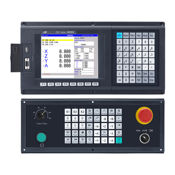
Milling Control System
Brand:
SZGH
| Category:
Control Systems
| Size: 13 MB
Table of Contents
Table of Contents
9
Chapter 1 Preface
14
Characteristics
15
Technical Specifications
15
System Operation Condition
16
G Code List
17
Chapter 2 Programming
19
Basic Concepts of Programming
19
Tool Movement Along Workpiece Parts Figure Interpolation
20
Feed Function
21
Part Drawing and Tool Movement
21
Coordinate System
22
Indicated Command Dimensions for Moving the Tool
24
Cutting Speed-Spindle Speed Function
25
Tool Function
26
Command for Machine Operations
26
Configuration of Program
27
Main Program & Subprogram
30
Program Run
30
Tool Figure and Tool Motion by Program
31
Tool Movement Range-Stroke
32
Chapter 3 G INSTRCUTIONS
33
Introduction
33
G Code List
33
Positioning (Rapid Traverse) (G00)
37
Linear Interpolation (G01)
38
Circular Interpolation (G02/G03)
40
Helical Interpolation (G02/G03)
43
Space Arc Interpolation G06
44
Dwell (G04)
45
Skip Function(G31,G311)
46
Reference Position
47
Return to Starting Point (G26,G261~G264)
48
Save Current Position (G25)
48
Return to Specified Position (G61,G611~G614)
48
Coordinate System
49
Machine Coordinate System (G53)
49
Workpiece Coordinate System(G54/G55/G56/G57/G58/G59)
50
Local Coordinate System (G52)
52
Plane Selection(G17/G18/G19)
54
Absolute and Incremental Programming (G90/G91)
54
Pole Coordinate Instruction(G15/G16)
55
Inch/Metric Conversion (G20/G21)
57
Feed Mode
58
Processing Mode (G60/G64)
59
Scaling (G36/G37)
60
Programmable Mirror Image (G11/G12)
61
Rotate Coordinate Instruction (G68/G69)
62
Tool Length Offset (G43/G44/G49)
65
Tool Offset(45/G46/G47/G48)
67
Tool Radius Compensation C (G40/G41/G42)
70
Details of Tool Compensation C
74
Inside and Outside
74
Tool Movement When Start-Up
74
Canned Cycle (G73-G89)
80
High-Speed Peck Drilling Cycle(G73)
83
Left-Handed Peck Rigid Tapping Cycle (G74)
85
Fine Boring Cycle (G76)
87
Canned Cycle Cancel (G80)
88
Drilling Cycle, Spot Drilling (G81)
89
Drilling Cycle Counter Boring Cycle (G82)
90
Peck Drilling Cycle (G83)
91
Right-Handed Peck Rigid Tapping Cycle (G84)
92
Boring Cycle (G85)
94
Boring Cycle (G86)
95
Back Boring Cycle (G87)
96
Boring Cycle (G89)
98
Example of Canned Cycle
99
Block Cycle (G22,G800)
101
Macro Program Instruction(G65/G66/G67)
102
Non-Mode Macro Command G65
102
Macro Program Instruction
103
Operators' Meaning
105
Arithmetic & Logic Operation
105
Local Variable
105
Global Variable
106
System Variable
106
System Parameter Variable
106
I/O Variable
106
Message Hint Dialog Box
106
Build Processing Program Automatically
107
User-Defined Macro Instruction (G110-G170)
108
Bolt Hole Circle Drilling Cycle
108
Inner Circle Groove Roughing Cycle (G110/G111)
109
Inner Circle Groove Fine Cycle (G112/G113)
111
Outer Circle Fine Milling Cycle (G114/G115)
113
Outer Circle Rough Milling Cycle (G116/G117)
114
Outer Rectangle Rough Milling Cycle (G132/G133)
116
Inner Rectangle Groove Roughing Cycle (G134/G135)
119
Inner Rectangle Groove Fine Milling Cycle (G136/G137)
121
Outer Rectangle Fine Milling Cycle (G138/G139)
122
Chapter 4 M INSTRCUTIONS
124
M Function (Auxiliary Function)
124
Program Stop(M00)
124
Optional Stop (M01)
124
End of Program (M02,M30)
124
Cycle of Program (M20)
124
Account of Workpiece(M87)
124
Unconditional Jump (M97)
124
Subprogram Configuration
125
Calling of Subprogram (M98)
125
End of Subprogram (M99)
125
Standard PLC M Command List
126
M Output Command List
126
Spindle Control (M03/M04/M05)
127
Spindle Gear Shifting(M41/M42/M43/M44)
128
Coolant(M08/M09)
129
Lubricate(M32/M33)
129
Chuck(M10/M11)
129
Huff(M59/M58)
130
Condition Output of Machine Tool(M65/M67/M69)
130
M Input Command List
130
Analog Speed of Spindle(S , SS)
131
Comprehensive Examples for Programming
131
Chapter 5 Special Application
132
Linear/Rack Tool Magazine (G120)
132
Umbrella/Hat Tool Magazine (G121/G122)
134
Usage for Automatic Tool Setting Gauge
137
Usage for Automatic Dividing Center
138
Chapter 6 Operation
139
Operational Panel
139
Function Menu
139
Editing Keyboard
139
Machine Control Panel
139
Manual Operation
143
Manual Continuous
143
Manual Increment
144
Manual Pulse Generator(Handwheel)
144
Manual Reference Position Return
145
Auto Operation
147
Automatic Processing Mode
147
Processing at Arbitrary Program Line or with Arbitrary Tool
148
Start from "Nth" Line(Block)
148
Start from "N**" Line
148
Start Program
148
Halt Program
148
Emergency Stop
148
Alarm
149
Indicator Light Output
150
DNC Function
150
Rs232-Dnc
150
Usb-Dnc
150
External Electrical Connection
150
Limitation
150
Software Limitation
151
External Switch for Limitation
151
Suggestion Usage
151
External Switch for Power ON/OFF
152
Diagnosis
152
Programming Operation
155
Editing
155
Copy
155
Delete
157
Rename
157
Information
157
Compile
158
Folder Management
158
Execute Program
158
Communication
158
U-Disk Management
158
Function Keys of USB-Disk
159
Management of Processing Program
159
Management of Parameters & Software
160
Chapter 7 Parameter List
161
User Parameter
162
Speed Parameter
167
Axis Parameter
177
Tool Parameter
186
Other Parameter
187
Workpiece Coordinate Parameter
195
How to Set up the Workpiece Coordinate System
196
How to Adjust the Offset Value after Set Well
197
Password
197
Redeem
198
Radius Compensation
198
Length of Redeem
199
Tool Sets List
200
Set Quantity
200
Screw Compensation
201
Chapter 8 Installation & Connection
204
System Installation
204
System Installation Dimension
204
System Rear View
205
Interface Connection Graph
206
Communication Socket (Female/Db9)
206
CN4 Turret Socket (Female/Db15)
207
CN9 Spindle Encoder Socket (Female/Db9)
208
CN3 IO1 Control Socket (Female/Db25)
209
CN10 IO2 Socket (Female/Db25)
210
CN16 IO3 Socket (Female/Db26)
211
CN5 XYZ Drive Socket (Male/Db25)
212
CN6 AB Drive Socket (Male/Db15)
213
CN11 Mpg/Handheld Box Socket (Male/Db15)
214
Daily Maintenance and Repair
218
Maintain
218
Ordinary Problem
219
Appendix I: Wiring Diagram of CN3 Plug
220
Appendix II: Wiring Diagram of CN10 Plug
221
Appendix III: Wiring Diagram of CN4 Plug
222
Appendix IV Operational Panel
223
Advertisement
Advertisement
Related Products
SZGH Categories
Control Systems
More SZGH Manuals
Login
Sign In
OR
Sign in with Facebook
Sign in with Google
Upload manual
Upload from disk
Upload from URL