Sign In
Upload
Manuals
Brands
Swegon Manuals
Chiller
BlueBox Zeta Rev Series
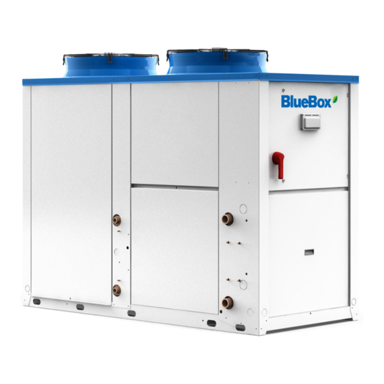
Swegon BlueBox Zeta Rev Series Manuals
Manuals and User Guides for Swegon BlueBox Zeta Rev Series. We have
2
Swegon BlueBox Zeta Rev Series manuals available for free PDF download: Service Manual, Installation, Use And Maintenance Manual
Swegon BlueBox Zeta Rev Series Service Manual (212 pages)
Brand:
Swegon
| Category:
Controller
| Size: 8 MB
Table of Contents
Operating Mode
2
Table of Contents
3
Operating Mode
3
Operating Mode
4
Introduction
9
General
9
Purpose of the Manual
9
IPG315D Controller Functions
9
Recommendations for Digital Security
9
Digital Services
10
Product Data Sheet Digital Services
10
Service" Branch
12
Programming the Parameters
13
Compressors
14
Auxiliary Heating
14
Water Pumps
14
Control Panel
15
Status of Inputs and Outputs
15
Software Functions
17
Unit ON/OFF Function Management
17
Set Point Management
18
Dynamic Set Point
18
Dynamic Set Point from External Air Probe
19
Parameter Value
19
Dynamic Set Point from Signal
21
Dynamic Set Point from Digital Input (Dual Set Point)
22
Energy Trend
23
Logs
24
Smart Grid Ready
26
Enable
26
Operating Mode 1
26
References on User Interface
28
Swegon Inside
29
Thermoregulation
30
Proportional Inlet Control
30
Outlet Control with Neutral Zone and PID
32
Time Bands
34
General
34
Time Band-Based Switch-Off
34
Energy Saving
35
Limitation of Refrigeration Capacity
36
Limitation of Refrigeration Capacity from Pressure Probe
37
Parameter Value
37
Limitation of Refrigeration Capacity from Amperometric Transducer
39
Limitation of Refrigeration Capacity from Digital Input
40
Limitation of Refrigeration Capacity from BMS
40
Circuits and Compressors
41
Starting and Stopping of the Compressors
41
Activation of the Compressors between the Circuits
42
Balance Sequence Criteria
42
Saturation Sequence Criteria
42
Capacity Balancing Principle
43
Capacity Saturation Principle
43
Management of Compressor with Inverter
44
Thermoregulation of Units with Inverter
45
Ventilation
48
Ventilation in Common or Separate
49
Management of Stepped Ventilation
50
Ventilation Management with Speed Adjuster
51
Floating Condensation Control
53
Night Shift System
55
Night Shift System with Floating Condensation Control
56
Fan Stop Prevention Function
57
Ventilation Alarms
58
Alarm Code
58
User-Side Pumps
59
Management of Unit Without Pumps or with One Pump
60
Management of 2 Pumps
61
Management of 3 Pumps
63
Management of the Pumps in Antifreeze Function
64
Pulse Function
65
Pump Alarms
66
User-Side Pump
67
Heat Recovery Pumps
68
Management of One or Two Heat Recovery Pumps
68
Heat Recovery Pump Alarms
68
Liquid Injection Valve
70
Oil Return
71
Oil Return for On-Off Compressors Connected in Parallel
71
Oil Return for Compressors Managed with Inverter
73
Heat Recovery
74
Enabling and Activation of Recovery
74
Recovery Management
75
Recovery Alarms
76
Desuperheater
77
Desuperheater Activation
77
Desuperheater Management
78
Antifreeze Control in Recovery System/Desuperheater
79
Management of the Pumps in Antifreeze Function
80
Pump down
81
Pump down During Switch-Off
81
Pump down Alarms
82
Refrigerant Leak Detector Management
83
Function Management
83
Password-Protected Counter Reset
84
Refrigerant Leak Detection Management
85
Stop Due to Refrigerant Leak
85
Refrigerant Leak Warning
85
Refrigerant Leak Alarms
86
Alarm Code
86
Free Cooling
87
Free Cooling with Air/Water Coil
88
Thermoregulation with the Free Cooling Function
90
3-Way Valve Management
92
Stopping of Compressors
93
Free Cooling with Dampers
94
Free Cooling with no Glycol
95
Free Cooling Alarms
97
Defrost
98
Simultaneous or Separate Defrost
99
Check of Conditions for the Defrost Cycle at Fixed Evaporating Temperature
99
Check of Conditions for the Defrost Cycle at Sliding Evaporating Temperature
100
Type of Defrost
101
Air Defrost
101
Preparation for Cycle Reversal
101
Refrigeration Cycle Reversal and Defrost
102
Preparation and New Cycle Reversal
103
Forcing of a Defrost Cycle
103
Defrost Alarms
104
Alarm Code
104
Anti Ice Circuit
105
Anti-Freeze Heaters
106
Heater Set Point and Differential
106
Reference Probe
107
Heater in Condensate Drip Tray
108
Auxiliary Heating
109
Conditions as the Air Temperature Changes
109
Auxiliary Heating with the same Set Point as Operation in Heat Pump Mode
110
Auxiliary Heating with Set Point Linked to Operation in Heat Pump Mode
111
Auxiliary Heating with Independent Set Point
112
ACS" Function
113
General
113
Enable/Disable Buttons and View Pages
115
Changes in Operation
115
ACS" Temperature Regulation
118
Alarm Code
119
Forced Exit from "ACS
120
Time Bands for "ACS" Function
121
Defrost Management
121
Max. Setpoint Compensation in Heating Mode
122
Heater Management
123
Anti Legionella Cycle
124
Vapour/Liquid Injection with Controller EXD-TEVI
126
Display and Keypad
126
Displayed Parameters
127
Managed Errors/Alarms
127
References on the Controller of the Unit
128
Flowzer
129
General
131
VP" Function
131
DT" Function
132
VDE" Function
135
VD" Function
136
VFPP" Function
137
VPS" Function
139
SMART Link
141
Parametrization of the Controller
141
Serial Connection
142
Smartlink
143
Serial Connection
143
Function Activation
143
Determination of Operating Mode (Only for Heat Pump Units)
146
Setpoint Calculation
146
Energy Meter
147
Viewing of Measured Parameters
147
Limitation of Absorbed Current Using "Energy Meter
148
Electronic Expansion Valve
149
Superheating Management
150
Control in High Superheating Conditions
150
Control in Low Superheating Conditions
151
Control in MOP Conditions
151
Control in LOP Conditions
152
Alarms
153
Introduction
153
Automatic/Manual Procedure and Alarm Reset
153
Unit Alarms
154
Flow Switch Alarm
154
Alarm Code
155
Antifreeze Alarms
156
Low Incoming Water Temperature Alarm
158
High Incoming Water Temperature Alarm
158
Low Ambient Temperature Alarm
159
Wrong Phase Sequence Alarm
160
Maximum/Minimum Voltage Alarm
160
Alarms for Expansion Modules Not Connected
161
Flowzer VFPP-VPS Alarm
161
Energy Meter Alarm
161
RTC" Clock Alarm
162
Internal Memory Alarm
162
Function Alarms
163
Pump Alarms
163
Ventilation Alarms
165
Recovery Alarms
166
Pump down Alarms
166
Refrigerant Leak Alarms
167
Alarms Concerning Refrigerant Leak Detector Sensor Maintenance
167
Free Cooling Alarms
168
Defrost Alarms
169
Fast Restart Alarms
170
ACS" Alarms
171
Alarms Relating to 2-Zone Function (GIT Option)
173
Tank Thermoregulation Alarms (TSS Option)
173
Auxiliary Heating Alarm
173
Circuit Alarms
174
High-Pressure Alarms
174
Parameter Value
174
High Discharge Gas Temperature Alarm
175
Alarm for Low Difference between High and Low Pressure
176
Probe Low Pressure Alarm
177
Forcing of Capacity Reduction from Low Pressure Probe
178
Forcing of Capacity Reduction from High Pressure Probe
179
Low Superheating Alarm
180
Expansion Module XEV20D Not Connected Alarm
180
Compressor Alarms
181
Compressor Overload Protection Alarm
181
Compressor Maintenance Alarm
181
Inverter Blocked Alarm
182
Alarm for Compressor Operation Outside Envelope
182
Inverter Offline Alarm
183
Probe Error Alarms
184
Temperature Probes
184
Pressure Probes
188
System Alarms
191
Alarms in Multilogic and Multifree Systems
191
Alarms in Systems with Smart Link+ Function
192
Configuration Alarms
193
Faq
194
Frequently Asked Questions
194
Switching the Unit on and off
194
Switch the Unit on and off from the Keypad
194
Switch the Unit on and off from External OK Signal
194
Switch the Unit on and off from the BMS
194
Changes in Operation
194
Change of Operating Mode from Cooling to Heating from the Keypad
194
Change of Operating Mode from Heating to Cooling and Vice Versa from External OK Signal
194
Change of Operating Mode from Heating to Cooling and Vice Versa from the BMS
195
Changing the Setpoint
195
Change of the Set Point in Cooling Operating Mode from the Keypad
195
Change of Set Point in Heating Operating Mode from the Keypad
195
Change of Set Point in Heating Operating Mode from the BMS
195
Change of the Second Set Point in Cooling Operating Mode from the Keypad
195
Change of the Second Set Point in Heating Operating Mode from the Keypad
195
Change of the Set Point from External OK Signal
195
Time Band Setup Procedure
196
Managing Recovery
197
Activate and Deactivate Recovery from the Keypad
197
Activate and Deactivate Recovery from External OK Signal
197
Change of the Recovery Set Point from the Keypad
197
ACS" Management
198
Switch the "ACS" on and off Using the Keypad
198
Switch the Air Conditioning System on and off Using the Keypad
198
Switch the "ACS" on and off by Means of an External OK Signal
198
Switch the Air Conditioning System on and off by Means of an External OK Signal
198
Editing "ACS" Setpoint
198
Management from BMS
199
RS485 Serial Connection
199
RS485 Serial Line
199
Enable ON/OFF from the BMS
199
Enable the Change of Operating Mode from the BMS
200
Enable the Change of Set Point from the BMS
200
Enable the Change of Operating Mode from I/O
200
Change of the Settings of the "BMS" Serial Communication
200
Resetting of Partial Counters
201
Resetting the Compressor Hours of Operation and Starts
201
Resetting the Number of Starts of the Compressors
201
Resetting of the Number of Hours of Operation of the Pumps
202
Controller Functions
203
Updating the Time and Date of the Controller
203
Changing the IP Addresses
203
Recovery of the "Service" Password
203
Replacements
204
Replacing the Electronic Expansion Valve Driver
204
WEB Pages
205
Access to Controller WEB Pages
205
Where to Find the Controller "MAC Address
205
Swegon Inside
206
The Unit Can be Connected to Swegon INSIDE
206
How to Access the Swegon INSIDE Screens in the Unit
206
How to Enable/Disable Swegon INSIDE
206
How to View the Certificate Expiry Date
207
Validity of ID Certificate for Connection to Swegon INSIDE
207
What to Do if the ID Certificate Has Expired or Is Missing
208
How to Gain Access to the Swegon INSIDE Portal
209
Information Displayed in the Swegon INSIDE Portal
210
Advertisement
Swegon BlueBox Zeta Rev Series Installation, Use And Maintenance Manual (88 pages)
Brand:
Swegon
| Category:
Chiller
| Size: 3 MB
Table of Contents
Table of Contents
3
1 Introduction
6
Conformity
6
Description
6
Symbols
6
Labels
7
2 Safety
8
General Safety Precautions
8
Discharge of the Safety Valves
9
Emergency Stop
9
Basic Rules
10
Water Flow Rate at the Heat Exchangers
11
Water Composition
11
Minimum Water Content in the System
12
Installing the Flow Switch
13
Unit Operating in Heat Pump Mode
13
Operation with Water to the Evaporator at Low Temperature
14
Operation in Heat Pump Mode with Low Temperature Water
14
Hydraulic Connection to the Heat Recuperator (DC Option)
15
Hydraulic Connection to the Desuperheater (DS Option)
16
Condensate Drain (Only for Heat Pump Units)
17
Refrigerant Leak Detector
18
Noise
19
Residual Risks
19
Safety Information on the Refrigerant Fluid
20
Hazards and Health Consequences
20
3 Receiving the Product and Storage
21
Reception
21
Transport
21
Handling
22
Storage
24
4 Ecodesign Conformity
25
Documentation Supplied with the Product
25
Units Conforming to All EC Requirements Including the Ecodesign Directive
25
Units Exempt from the Ecodesign Directive and in General Conforming to All EC Requirements
25
Partly Completed Machine
26
Attached Documents Envisaged with Regard to the Type of Unit
26
Efficiency Parameters Required for Conformity
26
Conformity of the Application
27
5 Product Description
28
Intended Use
28
Unintended Use
28
Control and Safety Devices
29
Principles of Operation
29
Structure
29
Specifications
29
Control Panels
30
Parametric Control
30
Programmable Control
32
Wiring Diagram
32
6 Installation
33
Dimensions and Weight
33
Installation Site
33
Installation
34
External Positioning
34
Noise Attenuation
36
Minimum Distances
36
Hydraulic Connections
37
System Components
39
Installation of Pressure Sensors
39
Installation of Temperature Sensor
40
Electrical Connections
41
Refrigeration Connections
42
Piping Implementation
42
LE Version: Unit Installed at a Higher Level than the Remote Exchanger
43
LE Version: Unit Installed at a Lower Level than the Remote Exchanger
44
LE/HP Version: Unit Installed at a Higher Level than the Remote Exchanger
44
LE/HP Version: Unit Installed at a Lower Level than the Remote Exchanger
45
Expansion Valve
45
Vacuum and Refrigerant Charge
46
Topping up with Oil
47
7 Commissioning
48
Preliminary Operations
48
Checking the Pre-Charge of the Expansion Vessel
49
Checking the Volume of the Expansion Vessel
50
Preliminary Operations for LE and LE/HP Units
51
Preliminary Operations for the Free Cooling no Glycol Circuit
51
First Starting
52
Hydraulic Tests
52
Start
52
Functional Tests
53
System Testing
54
Flowzer VP
54
Flowzer DT
58
Flowzer VDE
62
Flowzer VD
63
Flowzer VFPP
65
Flowzer VPS
68
Calibration of Safety Components
71
Checks During Operation
72
Alarms and Malfunctions
73
General Troubleshooting
73
Temporary Stop
75
Stop for Long Periods of Time
75
8 Maintenance
76
Adjustments
76
External Cleaning
77
Cleaning Traditional Finned Coils in Cu/Al
77
Cleaning the Microchannel Coils
78
Cleaning E-Coated Microchannel Coils
79
Internal Cleaning
80
Cleaning the Unit
80
Cleaning the Plate Heat Exchangers
81
Periodic Checks
82
Unscheduled Maintenance
83
Special Work
83
9 Decommissioning
84
Advertisement
Related Products
Swegon BlueBox Omega Sky
Swegon BlueBox Kappa Sky
Swegon BlueBox WESTERN Mu Echos A
Swegon BlueBox Tau SKY Hi HP
Swegon BlueBox Blueye
Swegon BlueBox Geyser Sky
Swegon PARASOL Zenith b 1800
Swegon BACnet gateway
Swegon BELIMO ZTH-GEN
Swegon Beta Series
Swegon Categories
Fan
Air Handlers
Fire and Smoke Dampers
Ventilation Hood
Control Unit
More Swegon Manuals
Login
Sign In
OR
Sign in with Facebook
Sign in with Google
Upload manual
Upload from disk
Upload from URL