Sign In
Upload
Manuals
Brands
SUTO Manuals
Accessories
S401
SUTO S401 Flow Meter Manuals
Manuals and User Guides for SUTO S401 Flow Meter. We have
2
SUTO S401 Flow Meter manuals available for free PDF download: Instruction And Operation Manual
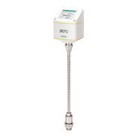
SUTO S401 Instruction And Operation Manual (44 pages)
Thermal Mass Flow Meter (Insertion)
Brand:
SUTO
| Category:
Measuring Instruments
| Size: 5 MB
Table of Contents
Table of Contents
3
Safety Instructions
5
Registered Trademarks
7
RF Exposure Information and Statement
8
Application
9
Features
9
Technical Data
10
General
10
Electrical Data
11
Output Signals
11
Accuracy
11
Volumetric Flow Ranges
12
Dimensional Drawing
13
Determine the Installation Point
14
Reserve Required Inlet and Outlet Sections
15
Installation
17
Installation Requirements
17
Installation Procedure
18
Calculate the Installation Depth
18
Install the Device
20
Remove the Device
21
Electrical Connection
21
M12 Connection Pins
22
Ethernet Connection
24
Signal Outputs
26
Analog Output
26
Pulse Output
26
Pulse Connection Diagrams (A1410)
28
Pulse Connection Diagrams (A1413)
28
Modbus Interface
30
Modbus Information
30
Connect Modbus/Rtu Devices to a Master
31
Modbus/Rtu Cable Length
31
Modbus/Rtu Wiring and Cable Type
32
Daisy-Chain Using RS-485 Splitter
33
Topology of Modbus/Rtu Daisy-Chain
34
M-Bus Output
35
Configuration
36
Use the Service App S4C-FS
36
Use the Display (Optional)
37
Start-Up
38
Operations
39
Menu Map
40
Calibration
42
Maintenance
42
Disposal or Waste
42
Advertisement
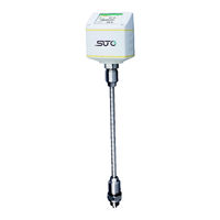
SUTO S401 Instruction And Operation Manual (40 pages)
Thermal mass flow sensor
Brand:
SUTO
| Category:
Accessories
| Size: 1 MB
Table of Contents
Table of Contents
3
1 Safety Instructions
4
2 RF Exposure Information and Statement
7
3 Application
8
4 Features
8
5 Technical Data
9
General
9
Electrical Data
10
Output-Signals
10
Accuracy
10
Volumetric Flow Ranges
10
6 Dimensional Drawing
12
7 Determining the Installation Point
13
8 Reserving Inlet and Outlet Sections
14
9 Sensor Installation
16
Installation Requirements
16
Installation Procedure
17
Calculating the Installation Depth
17
Installing the Sensor
19
Removing the Sensor
20
Electrical Connection
21
10 Sensor Signal Outputs
23
Analog Output
23
Pulse Output
23
Pulse Connection Diagram
25
Modbus Output
26
11 Sensor Display (Option)
27
Starting Process
27
Configuration Using the Display
28
12 Service App S4C-FS
29
13 Calibration
30
14 Maintenance
30
15 Disposal or Waste
30
16 Warranty
30
17 Appendix A - Analogue Output
32
18 Appendix B - Modbus Communication Example
34
19 Appendix C - LRC and CRC Calculation
36
Advertisement
Related Products
suto S 430
SUTO S452
SUTO S421
SUTO S450
SUTO S418
SUTO S401-S
SUTO S401-M
SUTO S401-H
SUTO S695 4100
SUTO S695 4103
SUTO Categories
Measuring Instruments
Accessories
Transmitter
Security Sensors
Data Loggers
More SUTO Manuals
Login
Sign In
OR
Sign in with Facebook
Sign in with Google
Upload manual
Upload from disk
Upload from URL