Sign In
Upload
Manuals
Brands
SUNWARD Manuals
Compact Loader
SWL Series
SUNWARD SWL Series Manuals
Manuals and User Guides for SUNWARD SWL Series. We have
2
SUNWARD SWL Series manuals available for free PDF download: Service Manual, Operation And Maintenance Manual
SUNWARD SWL Series Operation And Maintenance Manual (89 pages)
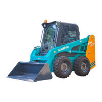
SKID STEER LOADER
Brand:
SUNWARD
| Category:
Compact Loader
| Size: 5 MB
Table of Contents
Table of Contents
2
Introduction
6
Models Available
6
About this Manual
6
Treatment of this Manual
6
Units
6
Definition of "Left" Side and "Right" Side
6
Precondition to Use the Machine
7
Signals
7
Security
9
Meaning of the Safety Signs
9
1General Signs
9
Acoustic Signs
11
Location of the Safety Labels
12
General Prevention
12
General Safety Rules
12
Clothing and Personal Protection
12
Enter and Leave the Machine
13
Prevention of Fire to Fuel and Oil
14
Prevention of Burns
14
Prevention of Damage of Working Equipment
15
Preventions During Operating
15
Machine Allowable Circumstance Condition
15
Safety Check before Working
15
Check the Working Site
15
Check the Machine
15
Starting the Engine
16
Moving the Machine
16
Moving on Slopes
17
Moving on Unusual Surfaces
17
Parking the Machine
17
Prevention of Electric Shock
18
Limits of the Machine
18
Transportation
19
Maintenance Prevention
19
General Rules
19
Running the Engine During the Maintenance
20
Working under the Working Equipment and Machine
20
Safety Rules for High-Pressure Oil and Hose
20
Prevention on the Starter and Alternator
21
Prevention of Battery Hazard
21
Precaution During Inflating the Tires
22
General Description of the Machine
23
Description of the Machine
23
Front View
23
Rear View
23
Machine Distribution
24
Specification
25
General Data
25
Overall Dimension
26
Engine
28
Electric System
28
Machine Identification
29
Machine Identification Plate and Product Identification Number (Pin)
29
Machine Serial Number
29
Engine Identification Plate
30
Serial Number of Chassis
30
Security Devices
30
Restrain Bar
30
Boom Locks
31
Radiator Overturning Protection Lock
31
Retainer of Auxiliary Control Pedal
31
Cabin Overturning Protection Lock
31
Seat
31
Instruments
33
Joysticks
36
Switches and Buttons
38
Cabin
40
Rear Window
40
Seat Belt
40
Fasten the Seat Belt
40
Undo the Seat Belt
40
Auto-Levelling System
41
Floatation System
41
Fuses
41
Relays
43
Documents Case
43
Engine Hood
43
Rear Cover
44
Battery
44
Operation of the Machine
44
Running-In
44
Checks before Operation
44
Starting the Engine
45
Normal Starting
45
Starting the Engine in Cold Weather
45
Warm up the Engine and the Hydraulic System
46
Stopping the Engine
46
Machine Movement
46
Operation of Working Equipments
49
Loading
50
Loading on Level Floor
50
Loading on Slopes
50
Digging
51
Levelling up
51
Parking the Machine
52
Acceleration
52
Transporting the Machine on Other Vehicles
53
Loading the Machine
53
Securing the Machine
53
Unloading the Machine
54
Lifting the Machine
54
Use of the Quick Coupler
54
Hitch the Bucket
55
Unhitch the Bucket
56
Ajust the Quick Coupler Mechanism
56
Use of Auxiliary Pedal
56
High Flow System
57
Maximum Immersion in a Fluid
57
Move the Machine with Towing Hook
57
Starting the Machine with Booster Cables
58
Long-Term Storage
58
Before Long-Term Storage
58
During the Period of Inactivity
59
After the Period of Inactivity
59
Maintenance
59
Requirement Service
59
Advice for the Maintenance
60
General Information for Carry out the Maintenance
61
Oil and Coolant at Corresponding Environmental Temperature
61
Capacities
63
Codification of the Main Changed Part
63
Torque for Screws
64
Tool List
64
Lubrication Points
65
Description Machine for Maintenance
65
Engine Description
65
Hydraulic System Description
66
Electrical System
66
Safety Belt
66
Maintenance Plan
66
Before Starting
69
Checking Engine Oil Level
69
Checking Engine Coolant Level
69
Checking Engine Fuel Level
69
Checking the Hydraulic Oil Level
69
Checking the Electric Cables
70
Checking the Tires
70
Checking the Safety Belt
70
Checking the Leaking of Oil
70
Checking the Quick Coupler
70
Ecking the Water and Sediments Separator
70
Every 50 Hours of Operation
71
Checking the Cooler Pipes
71
Checking the Coolant Level
71
Checking the Tire Pressure
71
Greasing the Pins of Boom and Cylinders
71
Checking the Wheel Nut Driving Torque
71
Every 100 Hours of Operation
72
Cleaning the Terminals of the Battery
72
Cleaning the Oil Tank's Breather
72
Checking the Cylinder Rods
72
Greasing All of Pins
72
Very 250 Hours of Operation
72
Checking the Gearing Chain Tension
72
Adjusting the Chain if Necessary
72
Checking the Fan Belt
73
Cleaning the Radiator
73
Checking the Oil Level in the Gear Chain
73
Changing the Engine Oil
73
Changing the Engine Oil Filter
73
Changing the Fuel Filter
74
Checking the Nut Torque of the Hydarulic Motor and the Hub Holding to the Chassis
75
Every 500 Hours of Operation
75
Claen the Fuel-Water Separator
75
Check the Tighteness of Pump Fixing Screws
76
Checking the Fluid Level of the Battery
76
Changing the Hydraulic Oil Filter
76
Every 1000 Hours of Operation
76
Changing the Oil in the Gear Chain Box
76
Changing the Hydarulic Oil and Clean the Suction
77
Changing the Air Filter
77
Checking the Pump's Pressure and the Valve
78
Changing the Hydraulic Oil Tank Breather
78
Checking the Tightness of the Cylinder Head Screw
78
Checking the Looseness of the Valve
78
Every 2000 Hours of Operation
78
Changing the Coolant
78
Checking the Starter and Alternator
78
When Required
78
Draining the Fuel Tank
78
Trouble Shooting
79
Optional Equipment
83
Security Measures
83
Security Measures for Installation
84
Performance of the Optional Equipment
84
Replacement of Optional Equipment
84
Connection of Hydraulic Circuit
85
Connection of Standard Hydraulic Circuit
85
Connection of High Flow Hydraulic Circuit (for Option with High Flow System)
85
Other Data
86
Electric Diagram
86
Electric Elements Chart
87
Hydraulic Diagram
88
Information of Manufacturer
89
Advertisement
SUNWARD SWL Series Service Manual (98 pages)
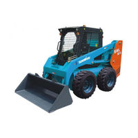
SKID-STEER LOADER
Brand:
SUNWARD
| Category:
Compact Loader
| Size: 4 MB
Table of Contents
Table of Contents
2
1 Introduction
5
Models Available
5
About this Manual
5
Treatment of this Manual
5
Units
5
Definition of "Left" Side and "Right" Side
5
Precondition to Use the Machine
6
Signals
6
2 Security
8
Meaning of the Safety Signs
8
General Signs
8
Acoustic Signs
11
Location of the Safety Labels
12
General Prevention
12
General Safety Rules
12
Clothing and Personal Protection
13
Enter and Leave the Machine
13
Prevention of Fire to Fuel and Oil
14
Prevention of Burns
15
Prevention of Damage of Working Equipment
15
Prevention of Electric Shock
15
Limits of the Machine
16
Maintenance Prevention
16
General Rules
16
Running the Engine During the Maintenance
17
Working under the Working Equipment and Machine
17
Safety Rules for High-Pressure Oil and Hose
18
Prevention on the Starter and Alternator
18
Prevention of Battery Hazard
18
Precaution During Inflating the Tires
19
3 General Description of the Machine
20
Description of the Machine
20
Front View
20
Rear View
20
Machine Distribution
21
Specification
22
General Data
22
Overall Dimension
22
Engine
23
Electric System
23
Pneumatic
24
Oils and Coolant
24
Capacities
24
Torque for Screws
25
Lubrication Points
26
4 Hydraulic System
27
Main Travel Pump
27
Illustration of Main Travel Pump Components
27
Pipeline Connection (for Testing) of Main Travel Pump
31
Set Pressure Data for Main Travel Pump
32
Travel Motor
34
Illustration of Travel Motor Main Components
34
Picture of Brake Oil Pipes' Connection
36
Rotation Direction of Travel Motor
36
Pressure for Arresting Gear's Start
36
Working Rear Pump
37
Outside View of Gear Pump
37
Breakdown Drawing of Gear Pump
38
Manifold Valve
38
Outside View and Illustration of Manifold Valve
38
Set the Data
39
Bucket-Lift Valve
40
The Outline and Illustration of Bucket-Lift Valve
40
Large Flow Control Block (Only for Large Flow System)
42
Outside View and Illustration of Large Flow Control Block
42
Set the Data
43
Operating Handle
43
Outside View and Data of Hand Lever
43
Pedal Operation Valve
49
Hydraulic Diagram
50
5 Electrical System
51
Installation Site 1
51
Installation Site 2
52
Diagram
53
Circuit Diagram
55
Power and Engine Circuit
55
Safety and Protection of Circuit
61
Monitor Circuit
64
Lamp and Float Control Circuit
66
Option Circuit
68
6 Travel System
69
Travel System Component
69
Wheel Shaft
70
Power Train Maintenance
72
Removal of the Front Wheel Shaft and Rear Wheel Shaft
72
Cleaning and Inspection
76
Repair or Replacement
76
Installation
76
7 Maintenance
78
Requirement Service
78
Advice for the Maintenance
78
Description for Machine Maintenance
79
Engine Description
79
Safety Belt
79
Maintenance Plan
80
Before Starting
83
Checking Engine Oil Level
83
Checking Engine Coolant Level
83
Checking Engine Fuel Level
83
Checking the Hydraulic Oil Level
83
Checking the Electric Cables
83
Checking the Tires
84
Checking the Safety Belt
84
Checking the Leaking of Oil
84
Checking the Quick Coupler
84
Ecking the Water and Sediments Separator
84
Every 50 Hours of Operation
84
Checking the Cooler Pipes
84
Checking the Coolant Level
85
Checking the Tire Pressure
85
Greasing the Pins of Boom and Cylinders
85
Checking the Wheel Nut Driving Torque
85
Every 100 Hours of Operation
85
Cleaning the Terminals of the Battery
85
Cleaning the Oil Tank's Breather
85
Checking the Cylinder Rods
85
Greasing All of Pins
86
Very 250 Hours of Operation
86
Checking the Gearing Chain Tension
86
Adjusting the Chain if Necessary
86
Checking the Fan Belt
86
Cleaning the Radiator
86
Checking the Oil Level in the Gear Chain
86
Changing the Engine Oil
87
Changing the Engine Oil Filter
87
Changing the Fuel Filter
87
Checking the Nut Torque of the Hydarulic Motor and the Hub Holding to the Chassis
88
Every 500 Hours of Operation
89
Claen the Fuel-Water Separator
89
Check the Tighteness of Pump Fixing Screws
89
Checking the Fluid Level of the Battery
89
Changing the Hydraulic Oil Filter
90
Every 1000 Hours of Operation
90
Changing the Oil in the Gear Chain Box
90
Changing the Hydarulic Oil and Clean the Suction
90
Changing the Air Filter
91
Checking the Pump's Pressure and the Valve
92
Changing the Hydraulic Oil Tank Breather
92
Checking the Tightness of the Cylinder Head Screw
92
Checking the Looseness of the Valve
92
Every 2000 Hours of Operation
93
Changing the Coolant
93
Checking the Starter and Alternator
93
When Required
93
Draining the Fuel Tank
93
Trouble Shooting
94
8 Information of Manufacturer
98
Advertisement
Related Products
SUNWARD SWL3210
SUNWARD SWTL 4518
SUNWARD SWL2820
SUNWARD SWTH634
SUNWARD SWL 2021 Series
SUNWARD SWL4018 2021
SUNWARD SWL2830
SUNWARD SWL3220
SUNWARD SWL3230
SUNWARD SWL4018
SUNWARD Categories
Excavators
Compact Loader
Construction Equipment
Drill
Temperature Controller
More SUNWARD Manuals
Login
Sign In
OR
Sign in with Facebook
Sign in with Google
Upload manual
Upload from disk
Upload from URL